
Introduction
This guide will walk through the correct installation procedure for the Grimm OffRoad JK ARB Twin Compressor Bracket.
Consumer Warning
All Grimm OffRoad products must be installed by a competent and qualified individual in accordance with the installation instructions intended for the product. Incorrectly installed products will void any warranties and may result in damage to the product or damage to the vehicle it was installed on. Read any provided instructions or guides and watch any available videos before attempting installation. If there are any questions, please contact Grimm OffRoad before starting installation.
Many products require the vehicle be properly raised and supported off the ground. The installer is responsible for confirming that this may be done in a safe manner and the correct equipment is available to perform the installation. Grimm OffRoad installation instructions assume the installer is able to properly and safely lift the vehicle.
Vehicles that have been modified will not perform the same as a stock vehicle. It is incumbent upon the owner of the vehicle to be aware of the differences the modifications will make to the driving characteristics of the vehicle. These may include (but are not limited to): changes in handling, braking, rollover angle, incompatibilities with the factory anti-lock braking systems, stability control systems, or traction control systems.
Supporting Parts
This Grimm OffRoad product is designed to be used in conjunction with an ARB Twin Compressor (Specifically the CKMTA12 ). It is important to review and familiarize yourself with the instructions provided with the compressor before beginning installation.
Tools
- 10mm Open End Wrench
- 13mm Open End Wrench
- 14mm Open End Wrench
- 17mm Open End Wrench
- 10mm Socket
- 13mm Socket
- 14mm Socket
- Torque Wrench
- Drill
- 17/32 Drill Bit
- 4mm Hex Bit
- Medium Strength Threadlocker
- Pipe Thread Sealant or Teflon Tape
- Zip Tie × 10
- Wire Crimper
- M8 Crimp-On Ring Terminal End × 4
- Heat Shrink Tubing (Optional)
Parts
- Compressor Mounting Plate
- Compressor Mount Gusset
- JIC4 Fitting
- Rivet Nut
- M8x1.25 40mm Long Hex Head Bolt
- M8x1.25 25mm Long Hex Head Bolt
- M8 Washer
- M8 Star Washer
- M10x1.5 Nut
- M6x1.0 25mm Long Hex Drive Flat Head Screw
- M6x1.0 Nylock Nut
- ARB Twin Air Compressor Part CKMTA12 (Required)
- ARB Manifold Part 171503 (Optional but required for air lockers)
- ARB Pump Up Kit Part 171302 (Optional but recommended)
- Auxiliary Switch System (Optional)
-
-
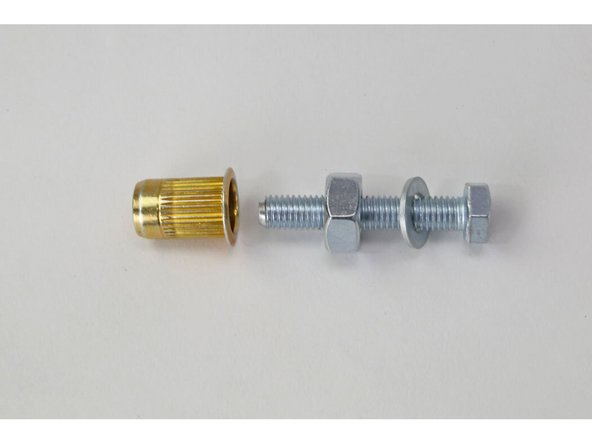
Verify that all parts shown in the pictures are present.
-
-
-
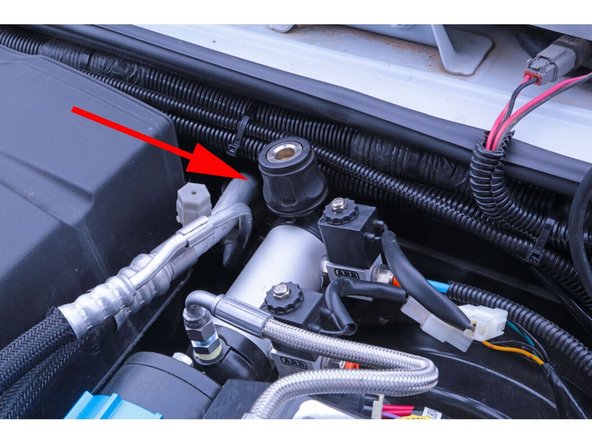
Locate these two points on the LH fender
-
The bolt indicated by the red arrow needs to be removed and set aside. Use a 10mm wrench or socket to remove it.
-
The hole indicated by the blue arrow needs to be drilled out with a 17/32″ drill bit.
-
-
-
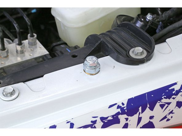
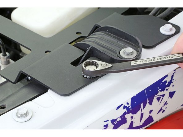
Assemble the rivet nut as shown with the M8 x 40mm hex head holt, M8 washer, M10 nut, and rivet nut, and insert it into the hole drilled earlier.
-
Tighten down the bolt until it sits flush.
-
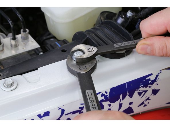
Hold the large nut with a 17mm wrench and tighten the bolt using a 13mm wrench. Continue to tighten until the rivet nut crushes and is tight in place, then remove the bolt.
-
This bolt and nut are only required for installation of the rivet nut.
-
-
-
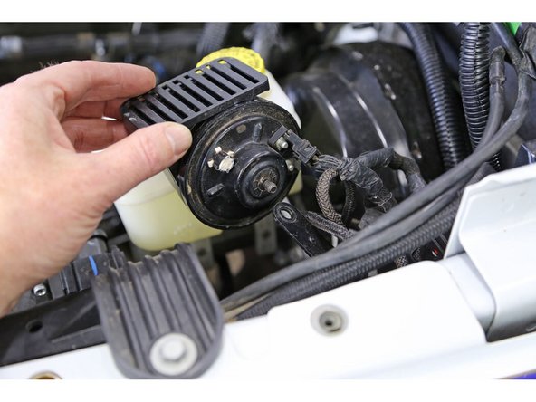
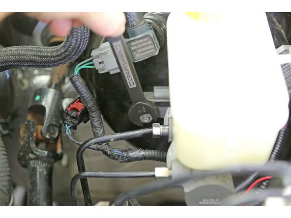
Remove the horn from it’s mount. Use a 10mm wrench to remove the nut.
-
Use a 13mm wrench or socket and loosen the RH nut on the brake master cylinder. You don’t need to remove it, just loosen it until you have a 1/4″ gap between the nut and the flange.
-
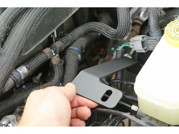
Install the compressor mount gusset onto the stud behind the nut you just loosened. The closed slotted hole should be facing up (as shown). The open slot should slide down between the nut and the master cylinder.
-
-
-
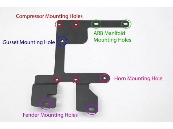
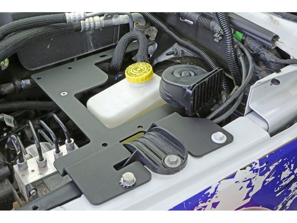
The four red circles indicate the ARB Twin Compressor mounting holes.
-
The green circles indicate the ARB Manifold mounting holes
-
The blue circle indicates the support gusset mounting hole
-
The pink circle indicates the horn mounting hole.
-
The purple circles indicate the holes for the fender mounts.
-
-
-
Set the compressor mounting plate onto the fender and the compressor mount gusset.
-
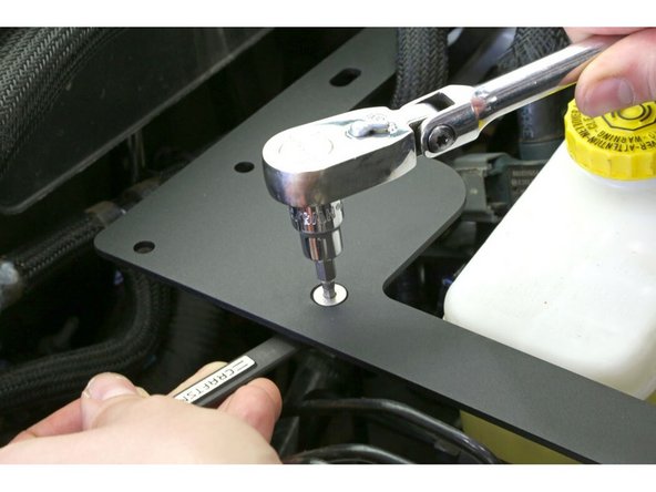
Install the M8 x 25mm hex head bolt, washer, and star washer into the rivet nut with a 13mm wrench and reinstall the original 10mm fender bolt into the rearward hole. Snug these up but do not fully tighten yet.
-
Install the M6 x 25mm flat head screw through the compressor mount and the compressor mount gusset. Install the M6 nylock nut on the backside and use a 10mm wrench and 4mm hex bit to snug up the screw (do not fully tighten yet).
-
-
-
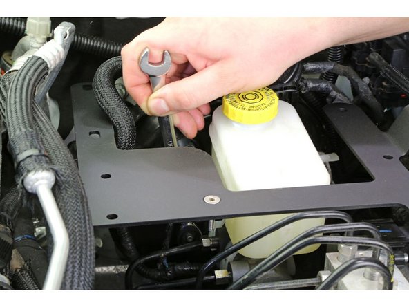
Tighten the nut holding the compressor mount gusset to the master cylinder flange.
-
Now tighten the support gusset screw to secure the gusset into place on the compressor bracket. Once the ARB twin compressor gets attached to this bracket, it will be impossible to get to this screw.
-
Torque to 11 lb-ft [15 Nm]
-
With the support gusset now secured in place, remove the fender bolts, loosen the master cylinder retaining nut, and carefully remove the compressor bracket and support gusset assembly from the Jeep being careful to keep the alignment of the two brackets.
-
-
-
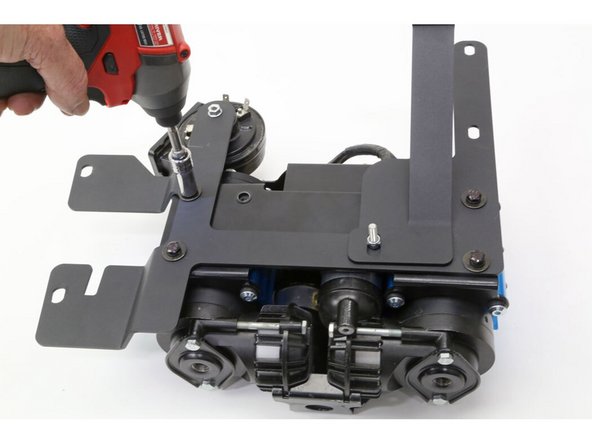
With the ARB Twin Compressor upside down, set the compressor bracket assembly onto the compressor and install using the ARB supplied mounting screws.
-
Use medium strength threadlocker on the screws to keep them from vibrating loose over time.
-
Torque mounting hardware to 7 lb-ft [9 Nm]
-
While we have full access to the compressor, mount up the horn and the ARB Manifold Kit (171503) if you will be connecting air lockers.
-
Torque mounting hardware to 7 lb-ft [9 Nm]
-
Use the supplied JIC4 fitting and high pressure stainless steel air line to connect the compressor to the manifold.
-
Make sure to use thread sealant on the NPT side of the JIC4 fitting which threads into the compressor.
-
-
-
Place the twin compressor and bracket assembly back into the vehicle.
-
Torque the new M8 fender bolt to 27 lb-ft [37 Nm]
-
Torque the stock 10mm fender bolt to 11 lb-ft [15 Nm]
-
Torque the master cylinder nut to 13 lb-ft [18 Nm]
-
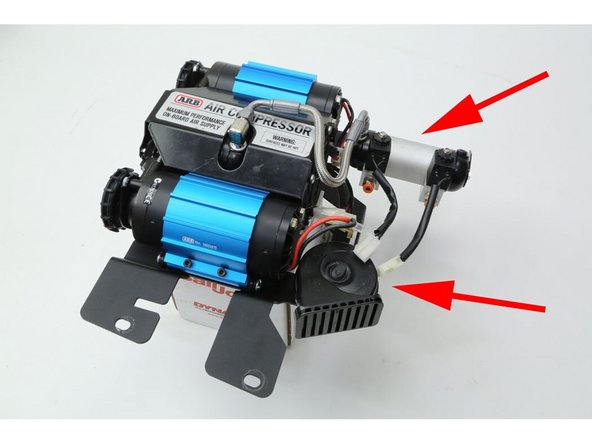
Check the master cylinder fill cap to ARB compressor clearance. If you have the compressor and compressor bracket slid as far forward as you can and the filler cap is still touching the ARB twin compressor, use a flat head screwdriver or something similar to bend the fan grille on the compressor in just enough to clear the filler cap.
-
-
-
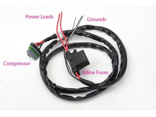
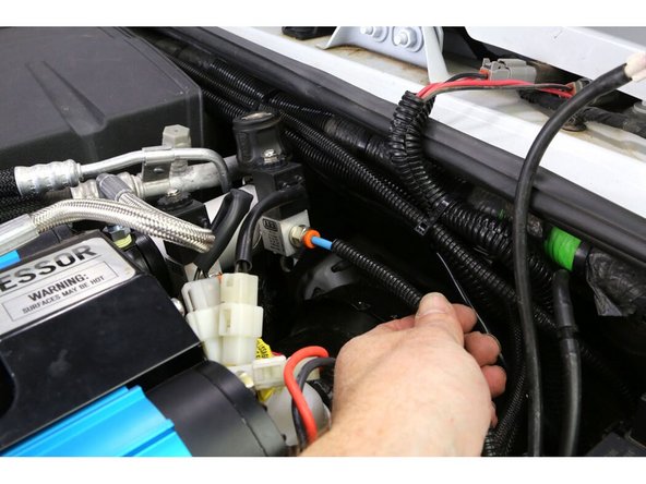
Attach the ARB main harness.
-
Plug the large plug into its mate on the ARB twin compressor.
-
Run the rest of the main harness along the firewall over to the battery box. Zip tie it in place every 6" or so with enough harness left to reach the battery terminals.
-
-
-
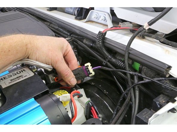
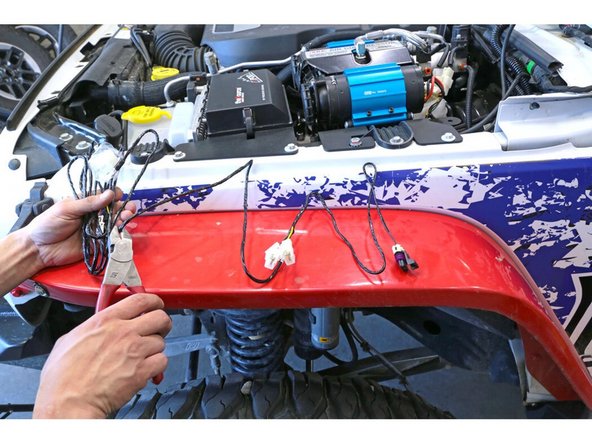
From the switch harness, connect the plug with the purple and black wire into the smaller compressor plug. This is the compressor activation circuit.
-
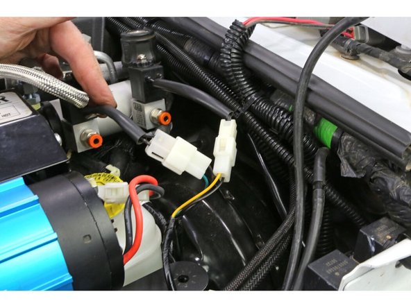
Plug the two white plugs on the switch harness into the manifold solenoids. It is good practice to plug the lead with the green wire into the front solenoid as a reminder that it is the lead for the front air locker and then plug the lead with the yellow wire into the rear solenoid as a reminder that it is the lead for the rear air locker.
-
Plug the ARB blue air lines into their respective solenoids.
-
The blue air line for the rear air locker plugs into the rear solenoid.
-
The blue air line for the front air locker plugs into the front solenoid.
-
-
-
If you are going to install the ARB twin compressor with the ARB switches, route the switch harness in through the firewall to the dash and wire according to the ARB instructions.
-
If installing an auxiliary switch system at the same time, instead of running the ARB harness into the cab and using the ARB switches, you can cut the ARB switch harness short and run the wires into the auxiliary switch control box.
-
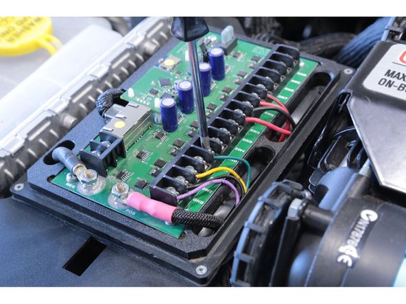
This installation is using an sPOD switch system, so we cut the switch harness short and are wiring it into the sPOD.
-
Purple wire is the compressor ON wire, we wired it into the SW1 position.
-
Black wire is the ground and grounds the other three wires, so it can go into any of the GND positions. We wired it into the first GND position.
-
Yellow wire is for the rear air locker, we wired that into the SW2 position.
-
Green wire is for the front air locker, we wired that into the SW3 position.
-
With the standard ARB harness you must first activate the compressor switch and the rear locker switch before you can activate the front locker switch. A big bonus to wiring the ARB switch harness into an auxiliary switch system is you by-pass the original ARB switch wiring and can now control all three switches independently.
-
-
-
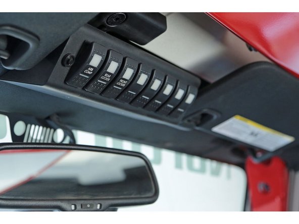
The first three switches on the sPOD can now be labeled to coincide with our wires in the sPOD module.
-
-
-
With everything else connected, we can now move back to the main harness at the battery box.
-
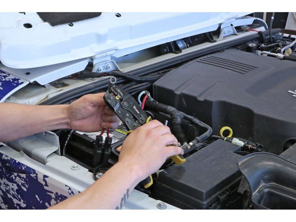
Trim the insulation back on the wires and crimp on ring terminal ends.
-
Add a piece of shrink wrap to the wire before putting the terminal on, then slide it up on the terminal shoulder and shrink it down with some heat for a little extra protection.
-
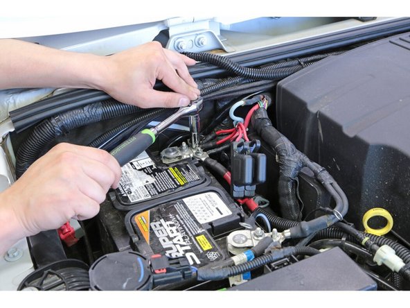
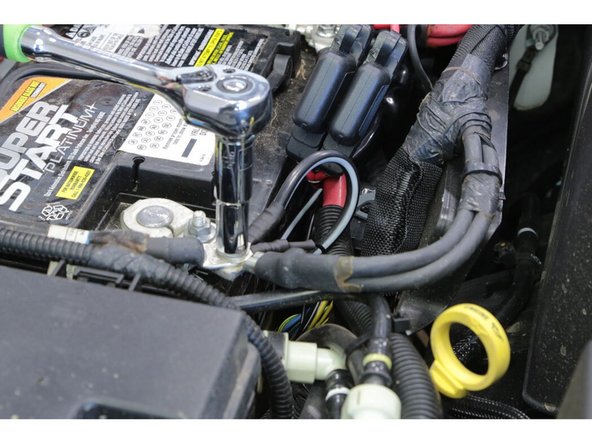
Install the two red terminal leads to the positive terminal of the battery.
-
Install the two black terminal leads to the negative terminal of the battery.
-
Always connect the positive lead(s) first and secure tight, then install the negative lead(s) last.
-
-
-
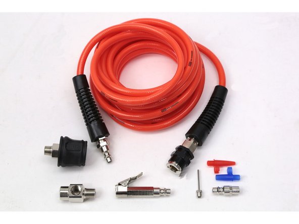
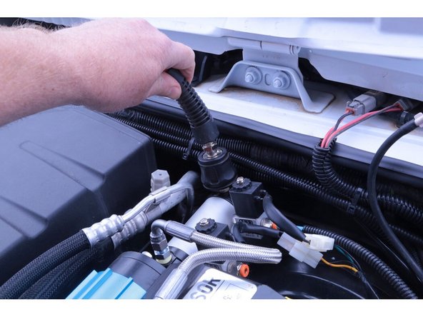
If using the ARB Pump Up Kit (171302), install the ARB air chuck at the back of the ARB manifold making sure to use thread sealant on the threads. Pointing it straight up will allow us to get at it by opening the hood and pushing the ARB hose in.
-
The Grimm OffRoad twin compressor mount for the JK/JKU makes installing the ARB twin compressor easy and tucks it nicely under the hood, keeping it protected from the elements and easy to get to.
-


![Torque mounting hardware to 7 lb-ft [9 Nm]](https://d3t0tbmlie281e.cloudfront.net/igi/grimmoffroad/HoIPxbfpkeHKbpW2.medium)

![Torque the new M8 fender bolt to 27 lb-ft [37 Nm]](https://d3t0tbmlie281e.cloudfront.net/igi/grimmoffroad/SbX2cLfNTuubcxOX.medium)

Installation is complete!
With any modified vehicle, or any vehicle used offroad, it is a good idea to check bolt torques periodically and visually inspect components regularly.
Installation is complete!
With any modified vehicle, or any vehicle used offroad, it is a good idea to check bolt torques periodically and visually inspect components regularly.
