
Introduction
This guide will walk through the correct installation procedure for the Grimm OffRoad Jeep Wrangler JL/JLU & Gladiator JT 4XE Charge Port Air chuck Conversion Kit.
Consumer Warning
All Grimm OffRoad products must be installed by a competent and qualified individual in accordance with the installation instructions intended for the product. Incorrectly installed products will void any warranties and may result in damage to the product or damage to the vehicle it was installed on. Read any provided instructions or guides and watch any available videos before attempting installation. If there are any questions, please contact Grimm OffRoad before starting installation.
Many products require the vehicle be properly raised and supported off the ground. The installer is responsible for confirming that this may be done in a safe manner and the correct equipment is available to perform the installation. Grimm OffRoad installation instructions assume the installer is able to properly and safely lift the vehicle.
Vehicles that have been modified will not perform the same as a stock vehicle. It is incumbent upon the owner of the vehicle to be aware of the differences the modifications will make to the driving characteristics of the vehicle. These may include (but are not limited to): changes in handling, braking, rollover angle, incompatibilities with the factory anti-lock braking systems, stability control systems, or traction control systems.
Supporting Parts
This Grimm OffRoad product is designed to be used in conjunction with an ARB Twin Compressor (Specifically the CKMTA12 ) when installed with the Grimm OffRoad GOR10013 Compressor Mounting Kit. Other compressor mounting kits may be used, but a longer air hose may be required in addition to extending the wire harness. Additional air hose lengths are available here.
ARB's CKBLTA12 brushless twin compressor can be used with this kit, however the provided Grimm OffRoad control harness is only applicable when using ARB's previous CKMTA12 twin compressor. When using ARB's brushless twin compressor, the switch can be connected following ARB's instructions with their included switch harness or via the switch harness kit provided in Grimm OffRoad's GOR10820 Brushless Twin Compressor Mounting Kit.
It is important to review and familiarize yourself with the instructions provided with the compressor before beginning installation.
We recommend also pairing with Grimm OffRoad's GOR10743 Air Hose Kit which includes the required air hose coupling and air hose.
Tools
-
-
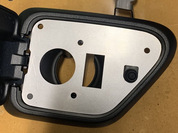
Verify that all parts shown in the pictures are present.
-
-
-
Remove the plug from the center of the Charge Port housing and the tether attaching it.
-
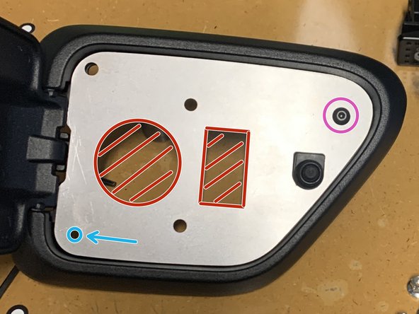
The center of the charge port housing needs to be cut out to allow installation of the bulkhead bracket assembly and switch. Take your time trimming and just cut a little at a time. It doesn't have to be perfect, but you don't want to cut too much. You can always trim more later if needed.
-
Cut as shown with a sharp box knife or something similar.
-
-
-
The base plate will cover the section that was cut out, and make sure enough material was removed for the air coupling and switch holes to be clear.
-
A new mounting hole needs to be added to the lower left of the Charge Port Housing.
-
Use one of the provided M5x0.8 screws and nuts to secure the base plate via the right upper hole.
-
Using the Base Plate as a template, drill the new hole with a 1/4" drill bit.
-
-
-
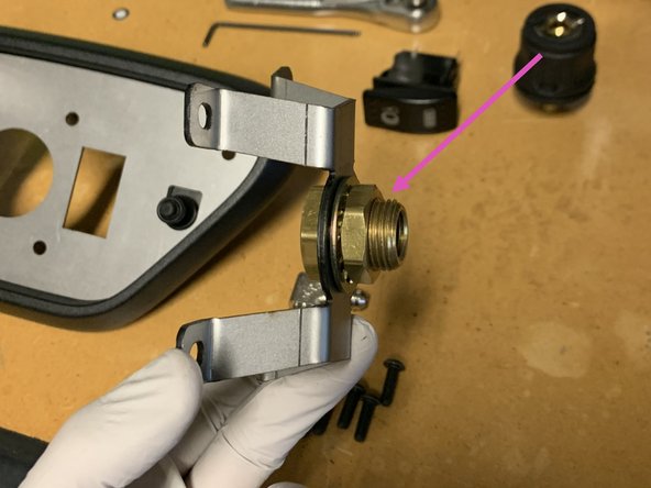
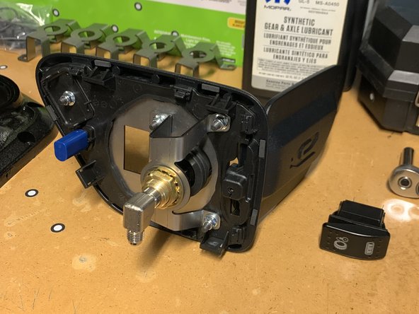
The Bulkhead Bracket Assembly should come with the brass bulkhead fitting pre-installed. Make sure the brass bulkhead fitting is oriented the correct direction as shown in the image. If it is installed backwards, there will not be room to close the 4XE door when fully assembled.
-
Install the 1/4” NPT x JIC4 90° fitting into the back of the bulkhead fitting as shown using a 9/16" socket/wrench. Make sure the fitting is pointed down. Use thread sealant on the NPT threads.
-
Note that NPT fittings are tapered fittings and must not be overtightened. If you can't get the fittings to point the correct direction, it is recommended to remove, use a couple additional wraps of Teflon tape, then reinstall.
-
Note that a 1" open end wrench can be used on the opposite side to prevent the bulkhead fitting from spinning while installing the NPT fitting.
-
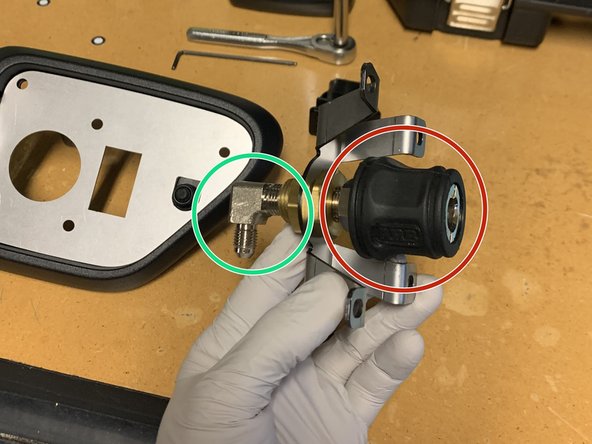
The air hose coupling can be installed into the bulkhead fitting at this time. We recommend using the Grimm OffRoad Air Hose Coupling which is included in our GOR10743 Air Hose Kit.
-
-
-
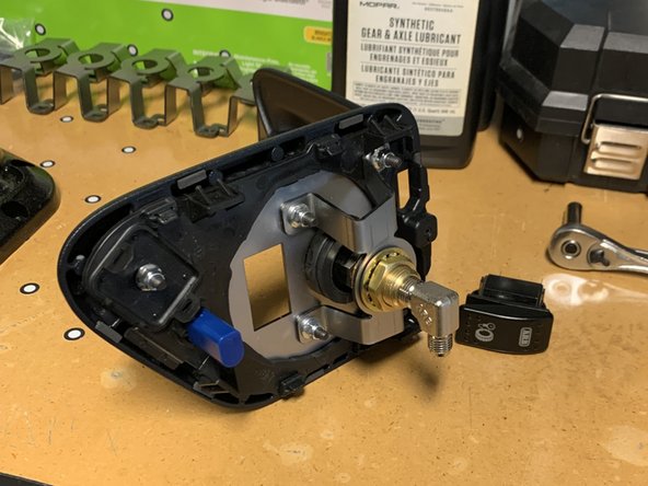
With the Base Plate lined up on the front of the Charge Port Housing, align the Bulkhead Bracket Assembly on the back.
-
Insert the five M5x0.8 16mm Hex Drive Button Cap Screws through the Base Plate from the front and secure with the M5x0.8 Flanged Nylocks on the back.
-
Torque with a T25 Torx Driver and 8mm socket/wrench to 35 lb-in [4 Nm] (Note, this is pounds per inch, not foot! Don't overtighten!)
-
The assembly should look as shown.
-
Confirm the orientation of the JIC4 Fitting.
-
-
-
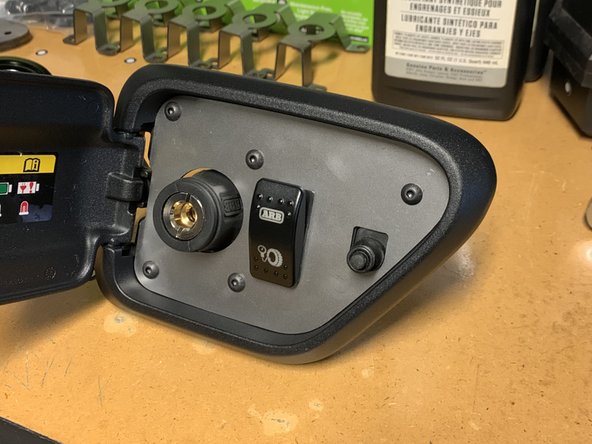
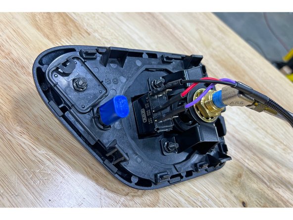
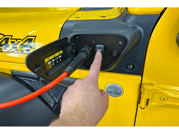
Push the ARB switch into the bracket until you hear it snap into place.
-
-
-
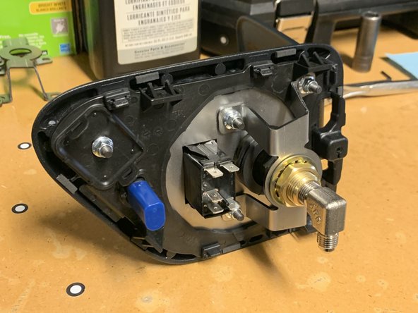
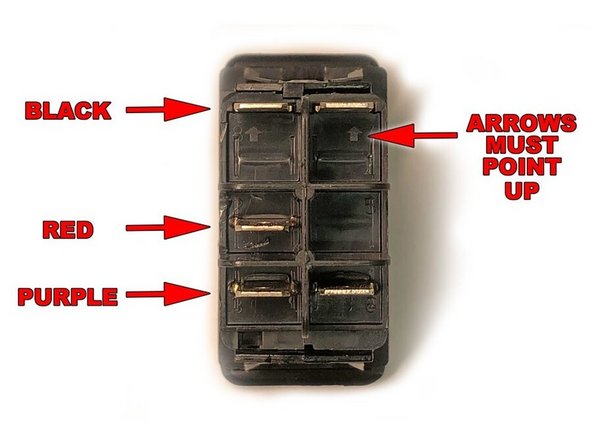
Be absolutely sure that you hook up this switch correctly according to the diagram in the first image. If wired incorrectly, you can short power directly to ground and damage the wiring in the compressor itself. ARB will not warranty your compressor if this happens.
-
Plug the wires from the Grimm OffRoad supplied switch wire harness into the back of the ARB compressor switch. The BLACK wire goes to the top terminal, the RED wire goes to the center terminal and the PURPLE wire goes to the lower terminal.
-
If connecting the ARB switch to an ARB brushless compressor, the provided Grimm OffRoad control harness will not be used. Follow the switch wiring instructions provided with the ARB brushless compressor or if using a Grimm OffRoad brushless twin compressor mounting kit, the included wire harness kit can be used.
-
The switch can be connected when installing the charge port housing in Step 11.
-
-
-
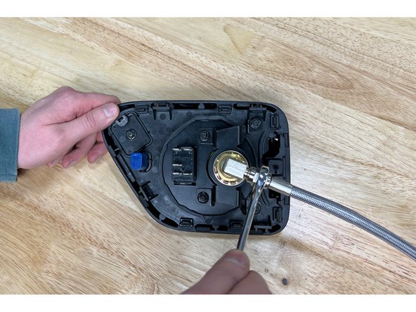
Attach the Stainless Steel Pressure Hose to the installed NPT fitting on the Bulkhead Bracket Assembly.
-
If connecting to an ARB brushless twin compressor with the Grimm OffRoad mounting kit, the provided Grimm OffRoad stainless braided air hose will not be used. Connect the air hose included with the Grimm OffRoad brushless twin compressor mounting kit to the NPT fitting on the Bulkhead Bracket Assembly when installing in Step 11.
-
The Stainless Steel Pressure Hose uses flared fittings and thread sealant is not required.
-
-
-
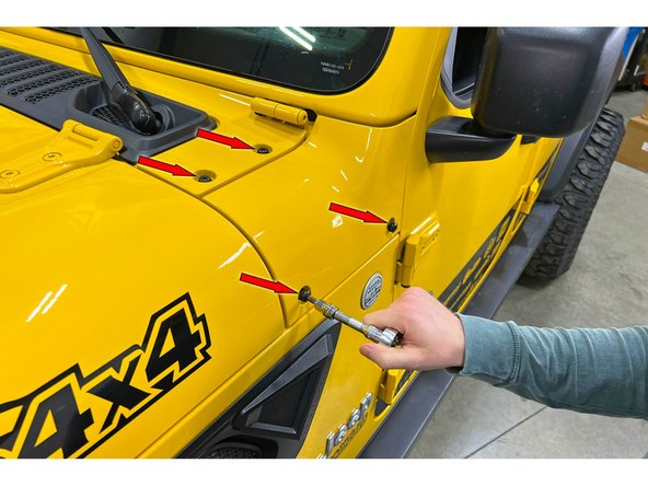
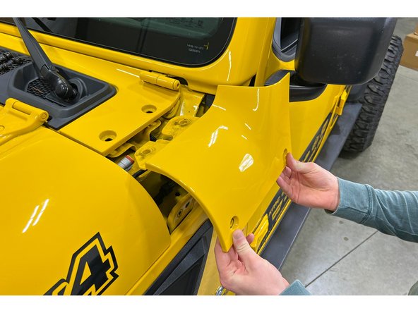
Using a T40 torx driver remove the 4 bolts holding the cowl trim piece on the driver side.
-
Lift out and remove.
-
-
-
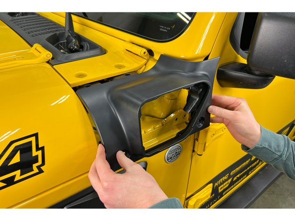
Install new provided left side Cowl Trim Panel.
-
Reinstall and torque all cowl trim hardware with a T40 Torx Driver to 10 lb-ft [13 Nm].
-
-
-
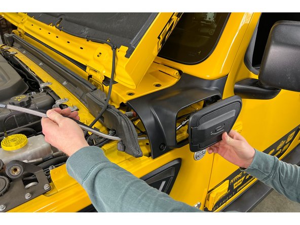
Route the wire harness and air hose from the Charge Port Housing Assembly through the Cowl Trim Panel and into the engine bay.
-
If using the ARB brushless twin compressor, the air hose and wire harness will be routed from the engine compartment to the 4XE Charge Port Kit. Connect as shown in steps 7 and 8.
-
The Charge Port Housing Assembly will snap into place in the Cowl Trim Panel.
-
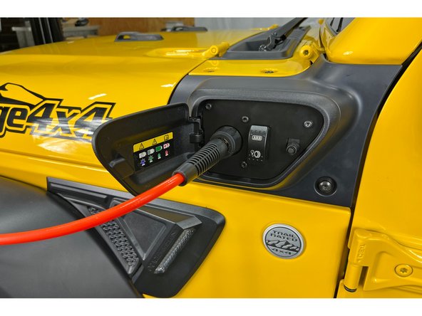
Connect the wire harness and air hose to the ARB Twin Compressor mounted with the GOR10013 Compressor Mounting Kit in your engine compartment.
-
If using a different ARB Twin Compressor mounting solution, a longer air hose may be needed and the included wire harness may need to be extended.
-
-
-
Start the vehicle and toggle the compressor switch to the on position. The compressor should turn on for a short period of time then turn off. If it doesn't, spraying the air connections with soapy water can help identify any leaks.
-
The fan on the ARB Twin Compressor will continue to run until the switch is turned off.
-


![Torque with a T25 Torx Driver and 8mm socket/wrench to 35 lb-in [4 Nm] (Note, this is pounds per inch, not foot! Don't overtighten!)](https://d3t0tbmlie281e.cloudfront.net/igi/grimmoffroad/EIMZsayVNhQjsPtr.medium)
Installation is complete!
With any modified vehicle, or any vehicle used offroad, it is a good idea to check bolt torques periodically and visually inspect components regularly.
Installation is complete!
With any modified vehicle, or any vehicle used offroad, it is a good idea to check bolt torques periodically and visually inspect components regularly.
