
Introduction
This guide will walk through the correct installation procedure for the Grimm OffRoad 2015+ F-150 Engine Skid Plate.
Consumer Warning
All Grimm OffRoad products must be installed by a competent and qualified individual in accordance with the installation instructions intended for the product. Incorrectly installed products will void any warranties and may result in damage to the product or damage to the vehicle it was installed on. Read any provided instructions or guides and watch any available videos before attempting installation. If there are any questions, please contact Grimm OffRoad before starting installation.
Many products require the vehicle be properly raised and supported off the ground. The installer is responsible for confirming that this may be done in a safe manner and the correct equipment is available to perform the installation. Grimm OffRoad installation instructions assume the installer is able to properly and safely lift the vehicle.
Vehicles that have been modified will not perform the same as a stock vehicle. It is incumbent upon the owner of the vehicle to be aware of the differences the modifications will make to the driving characteristics of the vehicle. These may include (but are not limited to): changes in handling, braking, rollover angle, incompatibilities with the factory anti-lock braking systems, stability control systems, or traction control systems.
Notes
- This skid plate requires removal of the factory active air dam controller.
- Installation is shown on a gas v8 truck. Diesel and EcoBoost trucks may look different with different coolers, but installation is the same.
- This skidplate is part of a complete skidplate group. This skidplate can be installed individually, but compatibility with other aftermarket skidplates is not guaranteed.
-
-
Verify that all parts shown in the pictures are present.
-
-
-
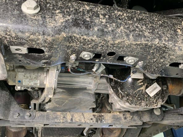
Using a 10mm wrench/socket, remove the 3 air dam mounting bolts that secure air dam to actuator motor on each side.
-
Remove the active air dam.
-
Using a 13mm wrench/socket, remove the 3 air dam actuator mounting bolts on each side of the trucks bumper.
-
Unplug and remove the actuators.
-
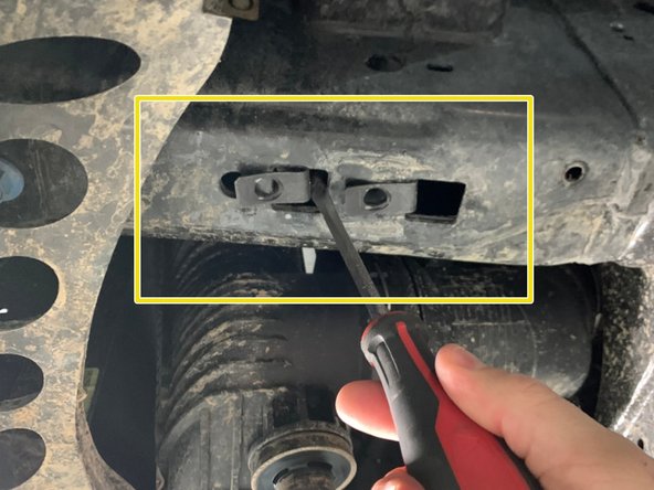
The 3 air dam actuator mounting bolts on each side of the truck may be re-installed if desired. If not, remove the nut clips.
-
Secure the air dam actuator wiring in a safe location.
-
-
-
The large lower engine/transmission cover will need to be removed. It is secured with four 15mm bolts and two 13mm bolts in the rear.
-
Using a 15mm wrench/socket, remove the forward two bolts.
-
Using a 15mm wrench/socket, remove the two bolts holding the metal support bracket to the crossmember.
-
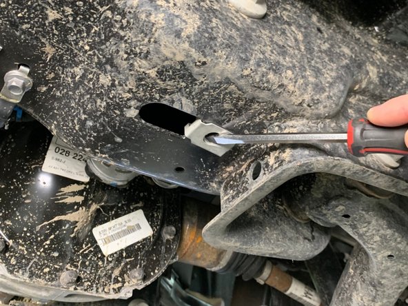
Using a 13mm wrench/socket, remove the two bolts, one on each side of the frame, holding the rear support brackets to the frame.
-
-
-
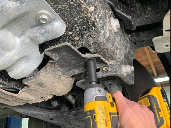
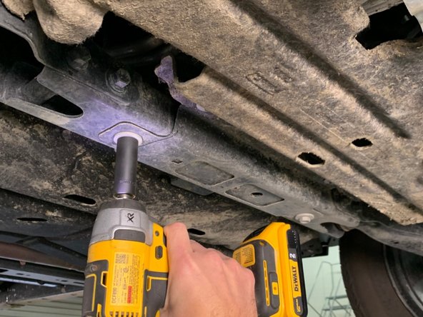
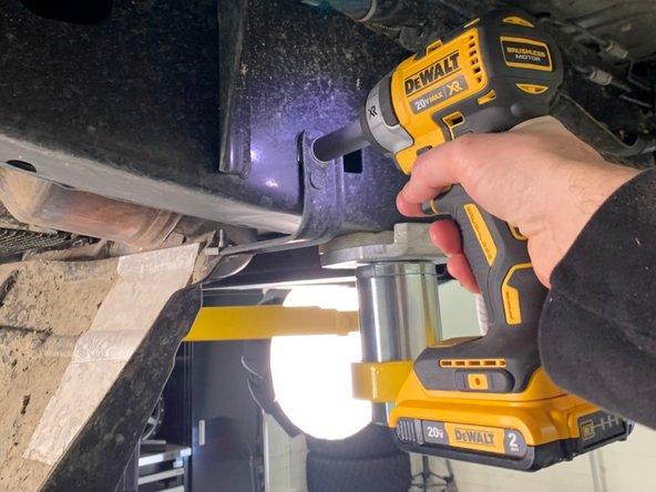
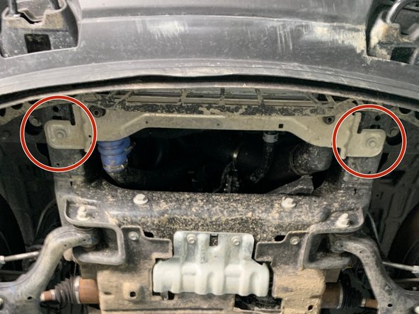
Using a 15mm wrench/socket, remove the two bolts holding the silver factory EPAS power steering skid plate to the front crossmember.
-
Re-install the hardware after removing the skid plate.
-
-
-
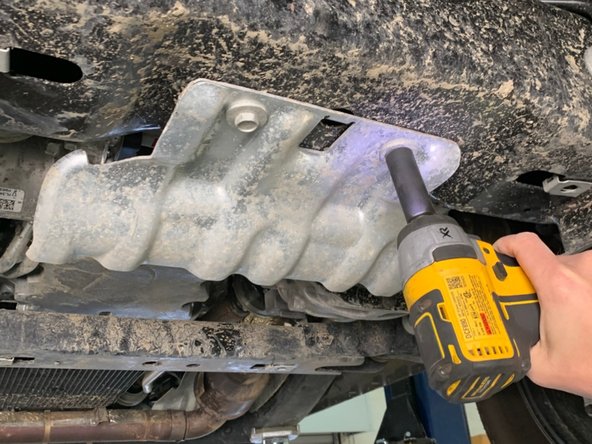
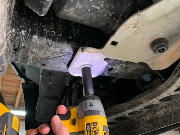
*If equipped* Using a 15mm wrench/socket, remove the two bolts securing the silver lower intercooler mount to the underside of the frame.
-
-
-
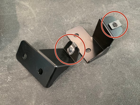
The factory clip nuts may be re-used. If the factory clip nuts were damaged, or there were no clip nuts on the truck, new clip nuts are provided.
-
Install clips on the engine skid mounting brackets as shown.
-
Install clip nuts on the frame where the silver radiator support installs. Install a clip nut in both locations as shown.
-
Verify there are clip nuts in the crossmembers both in front of and behind the front differential.
-
-
-
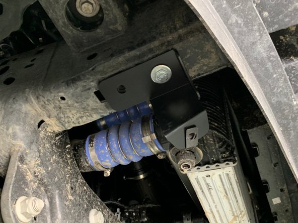
Attach the Engine Skid Brackets to the frame as shown using provided bolts and washers in the forward mounting hole. The skid mounting flanges should be oriented towards the front of the vehicle and in towards the center.
-
Leave hardware finger tight at this time.
-
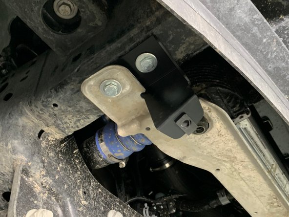
*If equipped* Re-attach the silver lower intercooler mount on top of the Engine Skid Brackets in the rearward hole as shown.
-
Install provided bolts and washers in the rearward hole, but leave finger tight at this time.
-
-
-
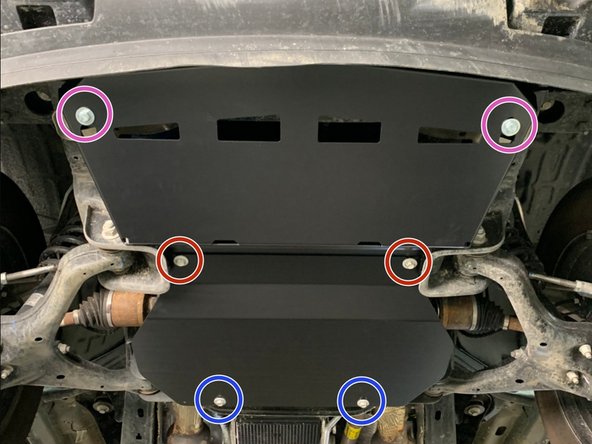
Loosely install two bolts and washers in the crossmember in front of the front differential.
-
Slide the Front Engine Skid over the loosely installed hardware on the crossmember, then push it up towards the Front Engine Skid Brackets and install hardware.
-
Slide the Lower Engine Skid over the Front Engine Skid, and install hardware in the rearward crossmember.
-
Verify all the skid plates and brackets are correctly aligned.
-
Torque all skid hardware to 35 lb-ft [48Nm] with a 17mm socket.
-


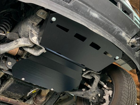
Installation is complete!
With any modified vehicle, or any vehicle used offroad, it is a good idea to check bolt torques periodically and visually inspect components regularly.
Installation is complete!
With any modified vehicle, or any vehicle used offroad, it is a good idea to check bolt torques periodically and visually inspect components regularly.