
Introduction
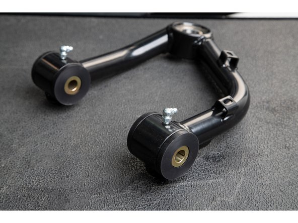
This guide will walk through the correct installation procedure for the Grimm OffRoad Ford Ranger Uniball Upper Control Arm.
Consumer Warning
All Grimm OffRoad products must be installed by a competent and qualified individual in accordance with the installation instructions intended for the product. Incorrectly installed products will void any warranties and may result in damage to the product or damage to the vehicle it was installed on. Read any provided instructions or guides and watch any available videos before attempting installation. If there are any questions, please contact Grimm OffRoad before starting installation.
Many products require the vehicle be properly raised and supported off the ground. The installer is responsible for confirming that this may be done in a safe manner and the correct equipment is available to perform the installation. Grimm OffRoad installation instructions assume the installer is able to properly and safely lift the vehicle.
Vehicles that have been modified will not perform the same as a stock vehicle. It is incumbent upon the owner of the vehicle to be aware of the differences the modifications will make to the driving characteristics of the vehicle. These may include (but are not limited to): changes in handling, braking, rollover angle, incompatibilities with the factory anti-lock braking systems, stability control systems, or traction control systems.
Notes
- These upper control arms are designed to be used with aluminum spindles only. If your truck has cast iron spindles, these will not fit! If you are unsure whether you have aluminum or cast iron spindles, aluminum are a very light silver color like in our installation photos. Cast Iron are coated black.
- These upper control arms are designed with additional caster over stock, in order to improve drive-ability, especially in cases where the vehicle has been lifted over stock height. It is important that when the vehicle is taken to be aligned that the alignment technician is familiar with modified vehicles and does not simply try to match the factory alignment settings.
- It is recommended that these control arms are used in conjunction with the Grimm OffRoad Billet Uniball Cap Set, part number 10019, in order to increase the longevity of the uniballs.
Tools
Parts
- Left Tubular UCA (Driver)
- Right Tubular UCA (Passenger)
- UCA Bucket Bracket × 2
- 2.125 x .565 x .188 Washer × 4
- Taper Adapter × 2
- Bearing Cap (.500 ID) × 2
- 1/2-20 x .875" 12 Point Flanged Cap Screw × 2
- 1.00 x .563 x 2.440 Pivot Sleeve × 4
- 1.625 x 1.000 x .850 Hat Bushing × 8
- 1.590 x 1.005 x .450 Load Ring × 4
- M12-1.75 Flanged Lock Nut × 2
- M12 Washer × 4
- Red Threadlocker
- Zerk Fitting × 4
- Zip Tie × 4
- Hose Protector × 2
-
-
Park the vehicle on a flat, level surface. Make sure the vehicle is in park or in gear, and that the parking brake is set. Raise the front of the vehicle and support the frame with jackstands.
-
Remove front wheels.
-
-
-
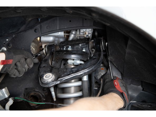
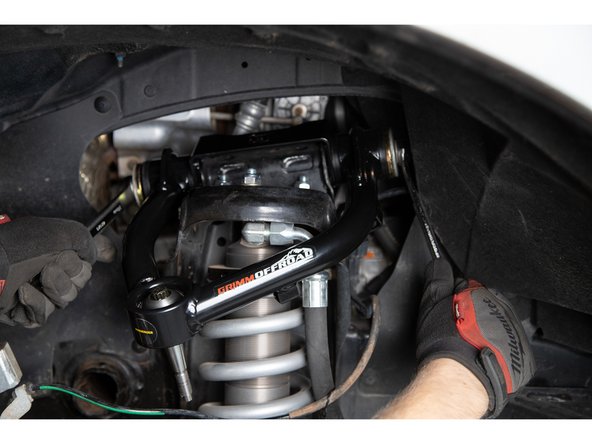
Carefully pull the ABS wire retainer from the upper control arm with a flat head screwdriver.
-
-
-
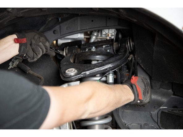
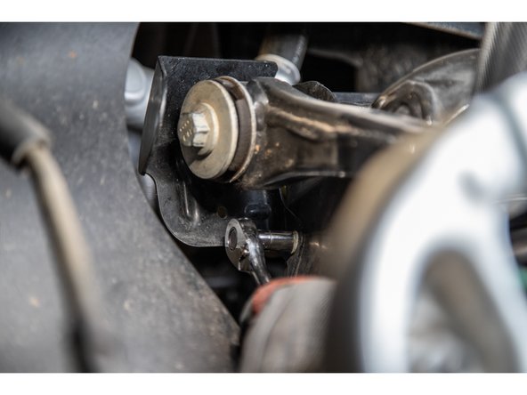
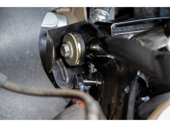
Remove the nut from the pivot bolt using an 18mm socket/wrench on the bolt head and a 21mm socket/wrench on the nut.
-
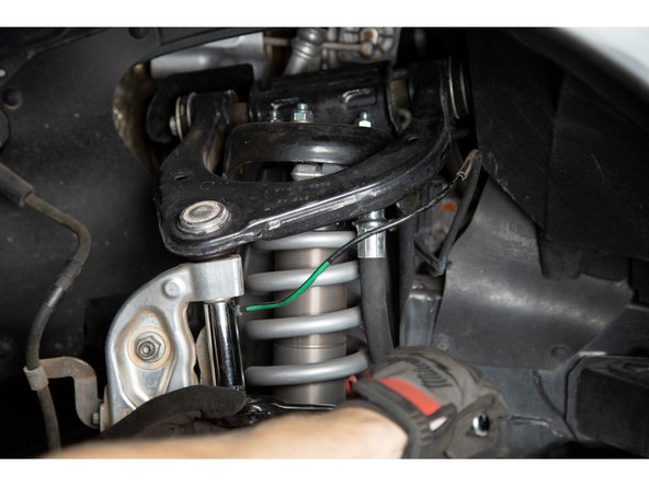
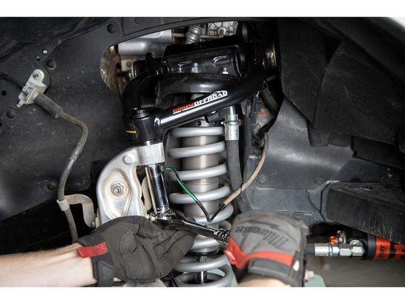
Using a 18mm socket or wrench, loosen the upper ball joint nut. Do not remove the nut, leave a few threads engaged.
-
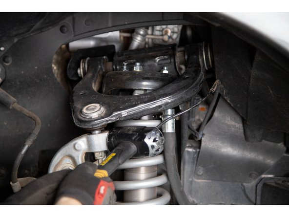
Strike the spindle with a large hammer where the upper ball joint stud engages the spindle. A couple quick strikes should separate the taper. Alternatively, a ball joint separator may be used.
-
-
-
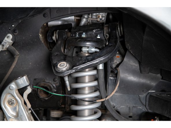
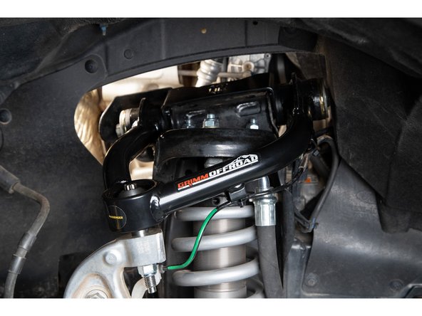
Separate the upper control arm from the spindle and support the spindle so that it does not overextend the CV joints when detached.
-
The upper control arm will have some bushing preload and will want to 'pop' up.
-
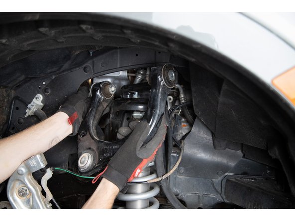
Slide the pivot bolt out from the back of the upper control arm.
-
There is a protective metal shield on the passenger side that is held on with one screw that will need to be removed before removing the pivot bolt.
-
-
-
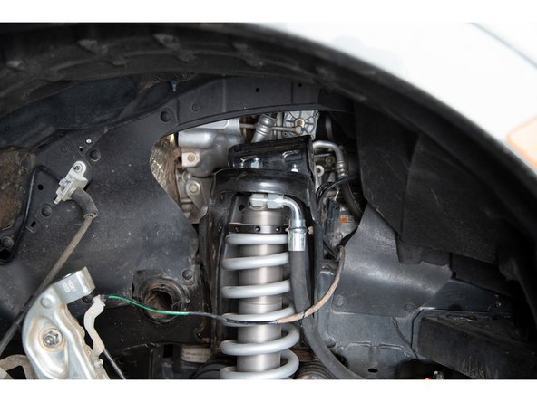
Remove the upper control arm assembly from the vehicle.
-
-
-
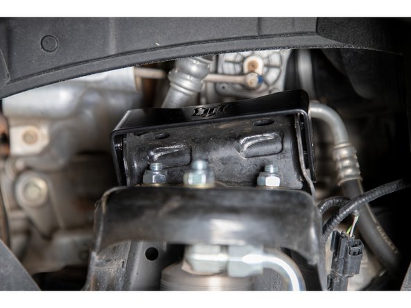
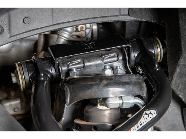
Slide the new upper control arm bucket bracket over the upper control arm frame mount. The cutout should be toward the motor.
-
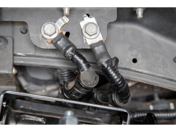
On the driver side, there are ground wires that will contact the UCA bucket bracket. To protect the wires, use the supplied hose protectors and zipties on the wires.
-
-
-
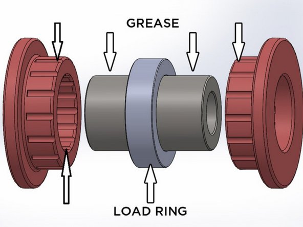
Apply grease to the inside of the Load Rings and slide them on to the Pivot Sleeves. They should sit in the center of the Pivot Sleeves.
-
Apply grease to the inside of the upper control arm pivot tubes and insert the Pivot Sleeves with Load Rings into the arms.
-
Apply grease to the inside and outside of the Hat Bushings, and slide them into the upper control arm pivot tubes.
-
Make sure the Hat Bushings are fully seated in the control arms, if they become too tight to push in, check to make sure the Pivot Sleeves are aligned properly. If the bushings are still too tight of a fit, use a large pair of pliers or a vice to fully seat the bushings, being very careful not to tear them.
-
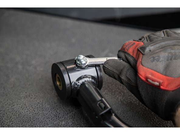
Install the supplied zerk fittings using a 5/16" wrench. Do not overtighten!
-
-
-
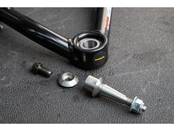
Install the taper adapter up from the bottom into the uniball. The tapered pin should point down, towards the spindle.
-
Place the domed top cap on top of the uniball and thread in a 12 point 1/2-20 cap screw.
-
-
-
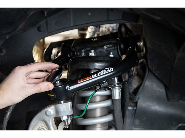
Install the Grimm OffRoad Upper Control Arms onto the vehicle. Note the orientation of the arms, the uniball should be closer to the rear of the vehicle.
-
Slide the frame bolt in from the back of the upper control arm. Make sure that the supplied washers are placed on the outside face (outer front and outer rear) of the hat bushings.
-
Grease the zerk fittings until grease is visibly coming out of the bushings and then tighten the pivot bolt.
-
Torque long upper pivot bolt to factory spec with an 18 and 21mm socket/wrench.
-
Reinstall the protective metal shield on the passenger side and torque to factory spec.
-
-
-
Pivot the tapered stem so that it lines up with the tapered hole in the spindle. Push the upper control arm downward so the tapered pin engages the spindle.
-
Take care when inserting the tapered pin into the spindle to not damage the threads on the pin. If you cannot re-orient the pin to line it up, do not force it into the spindle.
-
A second option is to remove the control arm and pin assembly from the frame and install the tapered pin into the spindle first, then use the leverage from holding the control arm to re-orient the pin and line up the mounts at the frame.
-
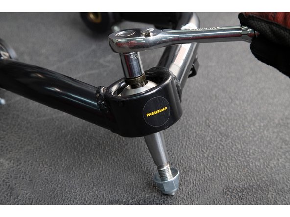
Use a 21mm socket/wrench to fasten the supplied nylock nut and 2 washers onto the tapered pin to get it to seat properly.
-
Do not use an impact wrench for this step!
-
If the pin spins, you may use the upper 12 point cap screw to prevent it from spinning.
-
Torque the nylock nut to 100 lb-ft [135 N-m].
-
-
-
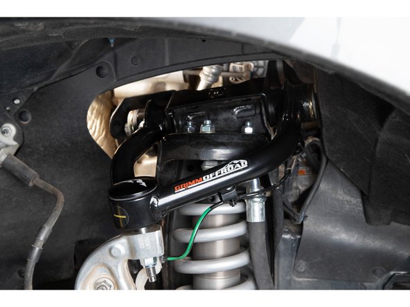
Re-connect the ABS lines to the Grimm OffRoad upper control arms.
-
Re-install wheels and put vehicle back on the ground.
-
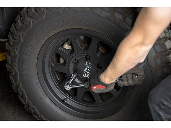
Torque lug nuts to factory spec.
-
-
-
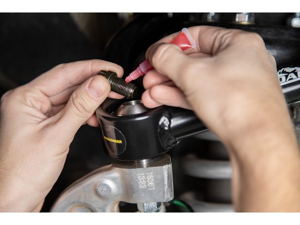
Remove the 1/2-20 12 point cap screws from the top of the uniballs. Apply provided threadlocker to the threads, and re-install.
-
Torque 12 point cap screws to 90 lb-ft [122 N-m]
-
Verify all hardware has been torqued.
-
Have vehicle professionally aligned.
-
-
-
If the 10019 Billet Upper Control Arm Cap Set was purchased, they can be installed now.
-
Re-check all bolt torques after the first 100 miles, and after every trip offroad.
-
Uniballs benefit from basic maintenance. Keep them clean and use a Teflon based dry lube to maximize their service life.
-
Grease the control arm bushings periodically, especially after wet or dusty trips.
-
When regreasing the upper control arm bushings the upper control arm bolt must first be loosened. After regreasing and purging the old grease, the upper control arm bolt can be retorqued.
-


![Torque 12 point cap screws to 90 lb-ft [122 N-m]](https://d3t0tbmlie281e.cloudfront.net/igi/grimmoffroad/VTP6DGIvfG34eVKd.medium)
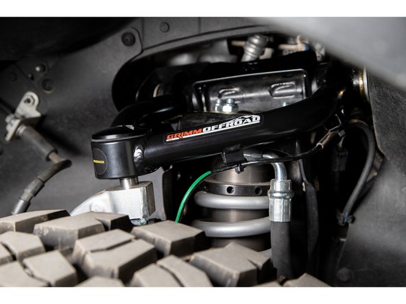
Installation is Complete!
Installation is Complete!
