
Introduction
This guide will walk through the correct installation procedure for the Grimm OffRoad JL and JT Front Inner Fenders.
Consumer Warning
All Grimm OffRoad products must be installed by a competent and qualified individual in accordance with the installation instructions intended for the product. Incorrectly installed products will void any warranties and may result in damage to the product or damage to the vehicle it was installed on. Read any provided instructions or guides and watch any available videos before attempting installation. If there are any questions, please contact Grimm OffRoad before starting installation.
Many products require the vehicle be properly raised and supported off the ground. The installer is responsible for confirming that this may be done in a safe manner and the correct equipment is available to perform the installation. Grimm OffRoad installation instructions assume the installer is able to properly and safely lift the vehicle.
Vehicles that have been modified will not perform the same as a stock vehicle. It is incumbent upon the owner of the vehicle to be aware of the differences the modifications will make to the driving characteristics of the vehicle. These may include (but are not limited to): changes in handling, braking, rollover angle, incompatibilities with the factory anti-lock braking systems, stability control systems, or traction control systems.
Tools
Parts
- Left Fender Liner Front Section
- Left Fender Liner Lower Front Section
- Left Fender Liner Lower Rear Section
- Left Fender Liner Rear Section
- Left Fender Liner Mounting Bracket
- Right Fender Liner Front Section
- Right Fender Liner Lower Front Section
- Right Fender Liner Lower Rear Section
- Right Fender Liner Rear Section
- Right Fender Liner Mounting Bracket
- M5-0.8 x 16mm Button Head Torx Screw × 22
- M6-1.0 x 16mm Button Head Torx Screw × 10
- M6-1.0 Flanged Hex Nylock Nut × 4
- M6-1.0 Clip Barrel Nut × 6
- M6 Oversized Washer × 10
-
-
Verify that all parts shown in the pictures are present.
-
-
-
We will be installing the passenger (right) side first.
-
Park the vehicle on a flat, level surface. Make sure the vehicle is in park or in gear, wheels are chocked, and that the parking brake is set. Raise the front passenger (right) side of the vehicle and support the frame or axle with a jack stand.
-
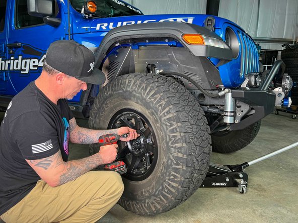
Using a 22mm socket/wrench, loosen the lug nuts and remove the front wheel/tire.
-
-
-
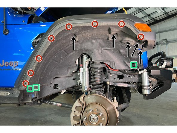
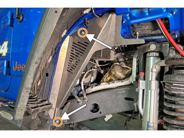
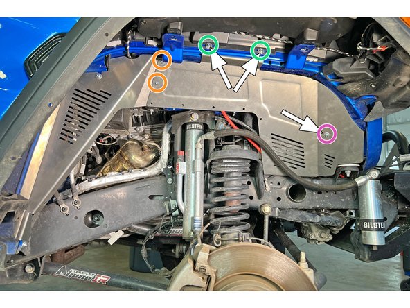
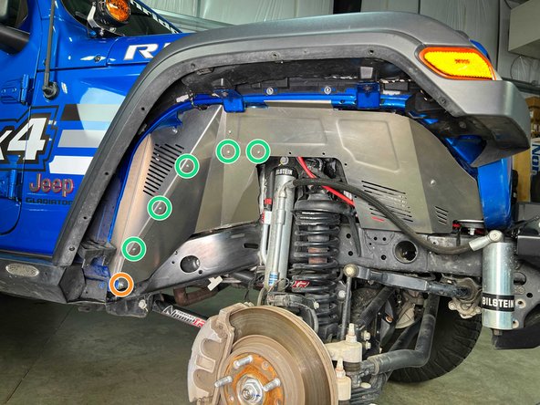
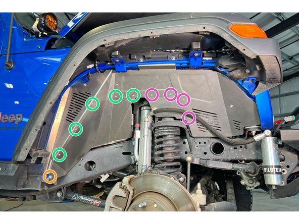
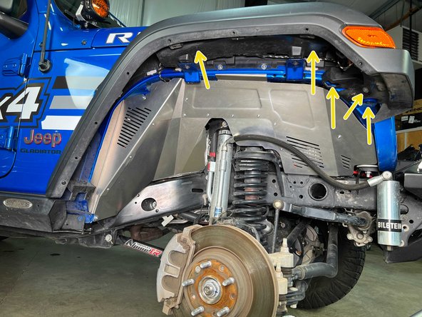
Remove the five fender liner screws with a 10mm socket/wrench (arrows in image). Save these as they will need to be reinstalled later.
-
Remove the three push pins with your trim removal tool. One is at the front lower of the inner fender and two are at the rear lower of the inner fender.
-
Remove the eight plastic rivets that secure the inner fender to the fender. A small punch can be used to push the center through, then the rivet can be pulled out.
-
-
-
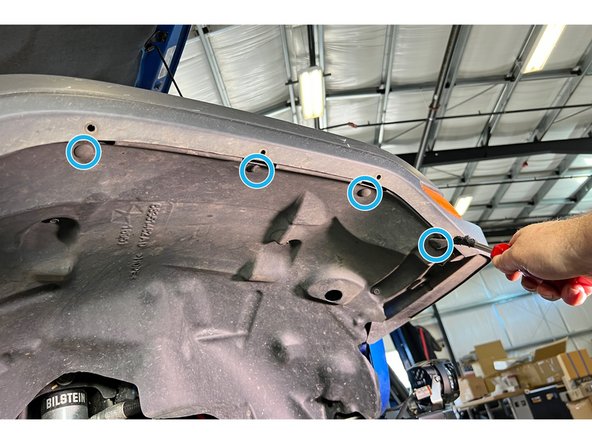
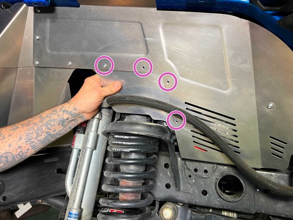
Remove the four upper push clips with your trim removal tool.
-
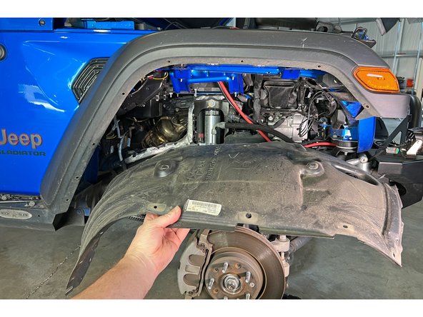
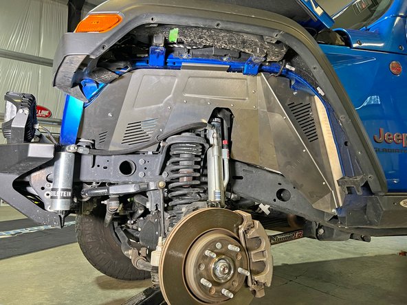
Remove inner fender.
-
-
-
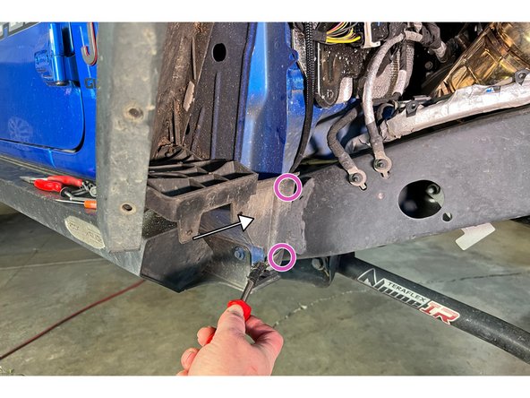
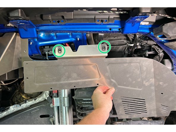
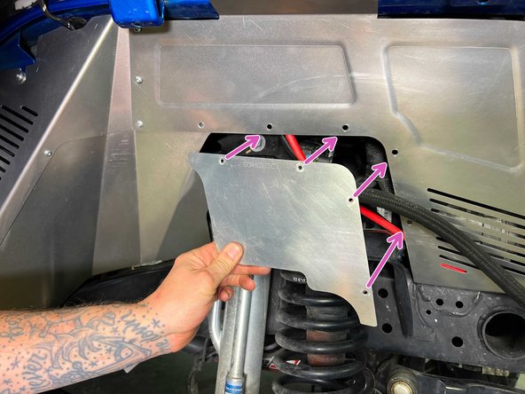
Remove the two push pins with your trim removal tool and remove the lower trim plate.
-
-
-
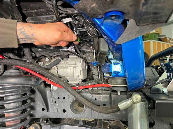
Detach the fender flare wiring connector from its mount.
-
-
-
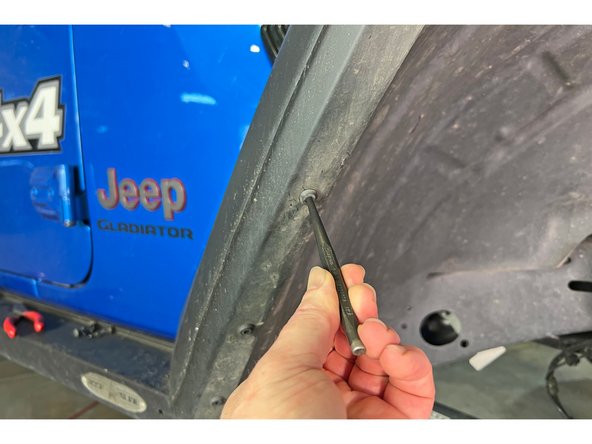
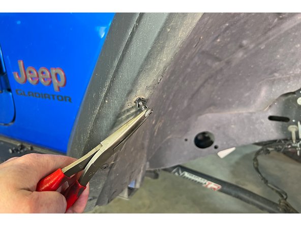
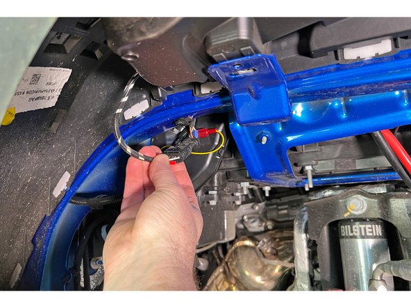
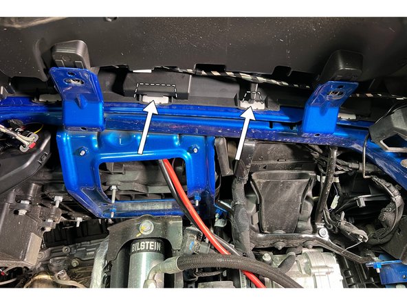
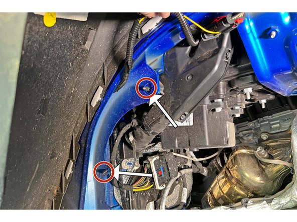
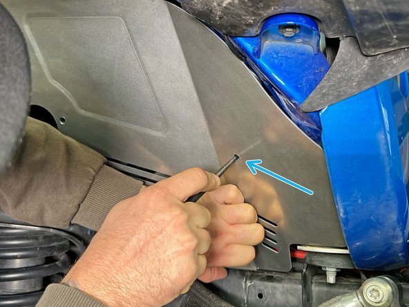
Using diagonal cutters, trim the plastic covering the center two fender flare clips as shown.
-
After trimming the plastic away, remove the fender flare clips.
-
-
-
With your trim removal tool, remove the wire harness locating push pins as shown at the rear of the fenderwell.
-
-
-
Tuck the flare wiring connector behind the top of the rear inner fender liner section when installing.
-
Install the rear inner fender liner section using two of the provided M6 screws with flat washers under the screw heads. Use a flanged nylock nut on the backside of each screw and leave loose for now.
-
Take care to check clearances all around making sure not to pinch any wires.
-
All of the inner fender liner screws will be left loose until all of the pieces are installed to ensure proper alignment.
-
-
-
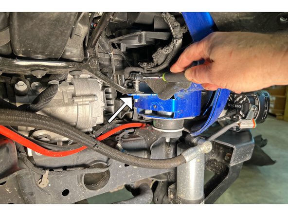
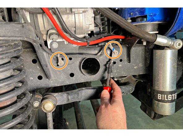
Using a 10mm socket/wrench, remove the screw behind the front body mount as shown.
-
With your trim removal tool, remove the wiring harness clips from the frame and secure the harness above the frame.
-
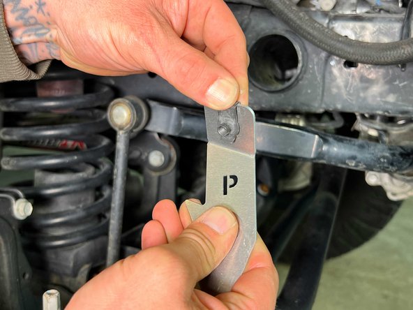
Install a clip barrel nut onto the "P" front mounting bracket as shown.
-
The mounting brackets are marked "P" for Passenger (right) side and "D" for Driver (left) side.
-
-
-
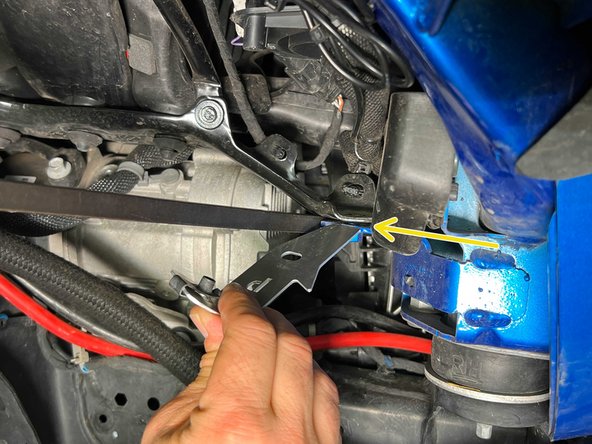
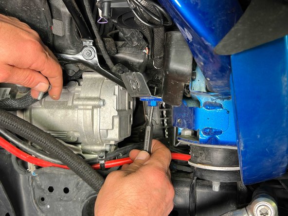
The fender mounting bracket should be slid between the body bracket and the inner support bracket. A pry bar can be used to help make a gap for the mounting bracket.
-
A small punch or alignment tool can be used to help line up the bracket.
-
Install using the screw removed earlier but only lightly snug it up for now so it can move, but with some friction, as we will need to align it with the front inner fender panel in the next step.
-
-
-
Install two of the clip barrel nuts onto the front inner fender liner section as shown.
-
Position the front inner fender liner section into place and install two of the provided M6 screws, with a washer under each screw head. The screws should go through the fender flare, the fender sheet metal, and then into the clip barrel nuts.
-
Take care to check clearances all around making sure not to pinch any wires.
-
Use a small punch or some sort of alignment tool to align the screw hole in the inner fender with the mounting bracket installed in the last step.
-
Once the mounting bracket is aligned, remove the inner fender and tighten the mounting bracket with a 10mm wrench/socket to 19 lb-ft [26 N-m]
-
-
-
Position the front inner fender liner section back into place and install two of the provided M6 screws, with a washer under each screw head. The screws should go through the fender flare, the fender sheet metal, and then into the clip barrel nuts.
-
Take care to check clearances all around making sure not to pinch any wires.
-
Install another M6 screw, with a washer under the screw head, through the front inner fender liner section into the front mounting bracket.
-
Install two of the provided M5 screws into the rear holes of the front inner fender liner section and loosely thread them into the rear inner fender liner section behind it.
-
-
-
Install the rear lower fender liner section behind the already installed rear fender liner section with five of the provided M5 screws as shown.
-
Use the M6 screw installed earlier to secure the lower part of the rear lower fender liner section.
-
Take care to check clearances all around making sure not to pinch any wires.
-
-
-
Note the orientation of the installed pem nuts in the front lower fender liner sections to tell the left and right side brackets apart. The smooth side should face out with the pem nuts pressed in from the back side.
-
Install the front lower fender liner section behind the already installed front fender liner section with four of the provided M5 screws as shown.
-
Take care to check clearances all around making sure not to pinch any wires.
-
With all the inner fender liner pieces now assembled, the screws can be tightened.
-
Tighten the M6 screws with a T30 Torx head driver (and 10mm socket/wrench if needed) to 8 lb-ft [10.5 N-m].
-
Tighten the M5 screws with a T25 Torx head driver to 5 lb-ft [7 N-m].
-
-
-
Reinstall the five fender liner screws removed in Step 3.
-
With a 10mm socket/wrench, torque hardware to 7 lb-ft [9 Nm]
-
-
-
Re-install the front wheel/tire and put the vehicle back on the ground.
-
With a 22mm socket and torque wrench, torque the lug nuts in a star pattern to 130 lb-ft [176 N-m].
-
-
-
Repeat Steps 2-17 for the Driver's side.
-


![With a 22mm socket and torque wrench, torque the lug nuts in a star pattern to 130 lb-ft [176 N-m].](https://d3t0tbmlie281e.cloudfront.net/igi/grimmoffroad/c22nlPtQh5TSHhFU.medium)
![With a 22mm socket and torque wrench, torque the lug nuts in a star pattern to 130 lb-ft [176 N-m].](https://d3t0tbmlie281e.cloudfront.net/igi/grimmoffroad/DwkZgEfvtxNBrnlb.medium)
Installation is complete!
With any modified vehicle, or any vehicle used offroad, it is a good idea to check bolt torques periodically and visually inspect components regularly.
Installation is complete!
With any modified vehicle, or any vehicle used offroad, it is a good idea to check bolt torques periodically and visually inspect components regularly.
