
Introduction
This guide will walk through the correct installation procedure for the Grimm OffRoad JL Rear Brake Line Kit.
Consumer Warning
All Grimm OffRoad products must be installed by a competent and qualified individual in accordance with the installation instructions intended for the product. Incorrectly installed products will void any warranties and may result in damage to the product or damage to the vehicle it was installed on. Read any provided instructions or guides and watch any available videos before attempting installation. If there are any questions, please contact Grimm OffRoad before starting installation.
Many products require the vehicle be properly raised and supported off the ground. The installer is responsible for confirming that this may be done in a safe manner and the correct equipment is available to perform the installation. Grimm OffRoad installation instructions assume the installer is able to properly and safely lift the vehicle.
Vehicles that have been modified will not perform the same as a stock vehicle. It is incumbent upon the owner of the vehicle to be aware of the differences the modifications will make to the driving characteristics of the vehicle. These may include (but are not limited to): changes in handling, braking, rollover angle, incompatibilities with the factory anti-lock braking systems, stability control systems, or traction control systems.
-
-
Verify that all parts shown in the picture are present.
-
The lines are side specific. The driver, or left side line retention bracket is stamped with a 'DB33'. The passenger, or right side line retention bracket is stamped with a 'PB33'. Be sure to identify the lines before installation.
-
-
-
These brake lines are best to install with the suspension fully extended on a vehicle lift or on jack stands. This way you can route and secure the brake lines and wheel speed sensors in a manner that prevents them from being over-extended.
-
It is advised to read the instructions thoroughly before beginning. Brake fluid will begin leaking when the stock brake lines are removed so it is best to work quickly to get the new brake lines installed.
-
-
-
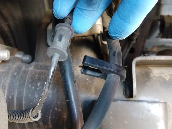
Unclip the wheel speed sensor wire from the brake line. There are four clips per side.
-
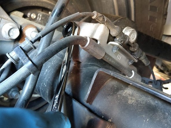
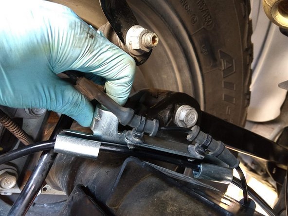
Loosen the axle side retaining bracket with a 13mm wrench.
-
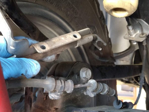
Remove the two push in studs that secure the wheel speed sensor wire to the brake line retaining bracket.
-
With the wheel speed sensor wire separated from the brake line, move the wire as out of the way as possible.
-
-
-
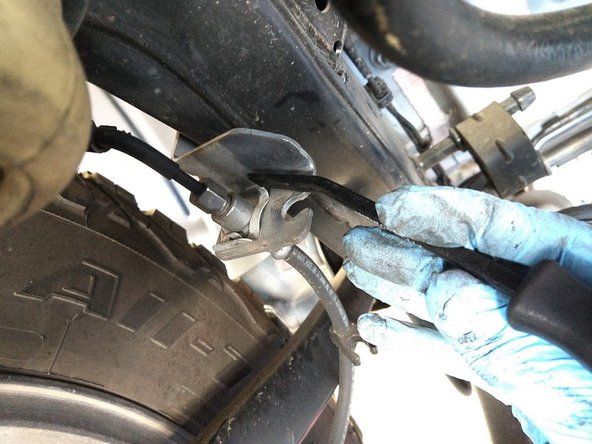
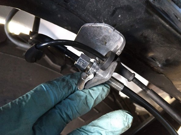
Remove the clip securing the brake line to the frame side bracket with a pry bar or flat head screwdriver.
-
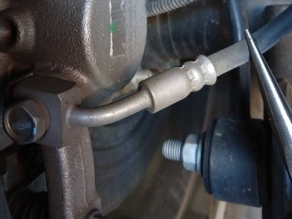
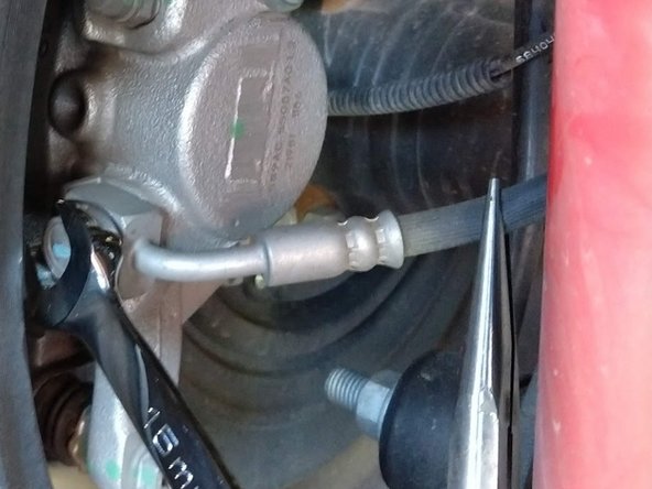
We recommend pinching off the factory brake hose close to the caliper with a pair of hose pinch off pliers. If these are not available, a pair of needle nose Vice Grip pliers, or a pair of conventional needle nose pliers with a zip tie around the handles can work.
-
Be prepared to catch and clean up brake fluid.
-
Remove the caliper side banjo bolt with a 15mm wrench or socket.
-
-
-
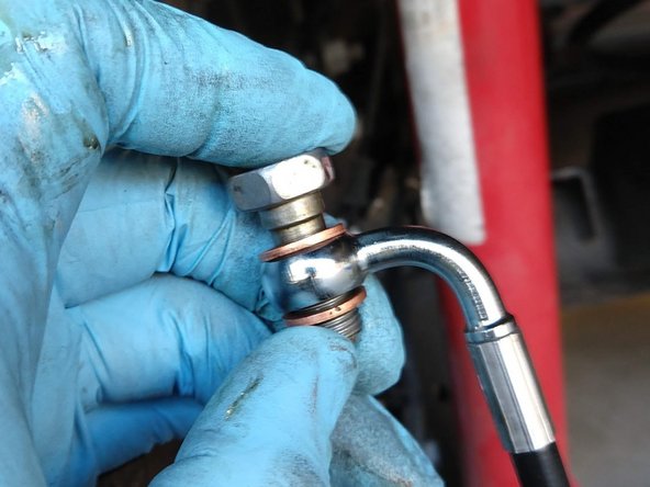
Using a new copper crush washer on each side of the banjo fitting, insert the banjo bolt in the direction of the line as shown.
-
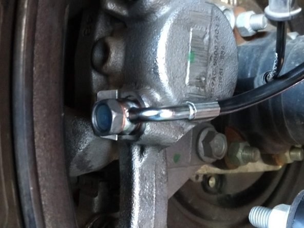
Thread the banjo bolt into the caliper, with the new brake line running along the caliper, towards the front of the vehicle.
-
Torque the caliper side banjo bolt with a 15mm socket to 26 lb-ft [35 Nm].
-
Route the new line forward, following the path the old line took. Pull the old line forward in front of the axle and let it hang from the frame side bracket.
-
If installing the GOR10829 brake lines, the lines will be routed up and forward instead.
-
Secure the brake line retaining bracket to the axle, but leave the mounting bolt loose at this time.
-
-
-
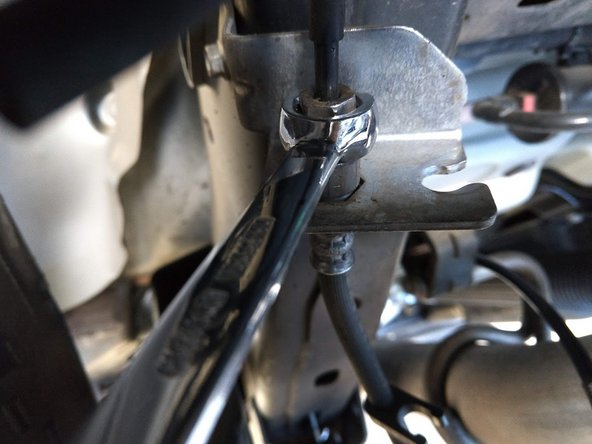
Loosen the frame-side hard line fitting with a 12mm flare nut wrench and a 16mm open end wrench. Remove the factory brake line.
-
Be prepared to catch and clean up brake fluid.
-
Insert new Grimm OffRoad brake line through the frame side bracket like the factory line. Thread the hard line nut into the Grimm OffRoad brake line. Often the first threads on the hard line nut are slightly deformed and care must be used to make sure the threads are started correctly and not cross threaded.
-
Fully tighten the connection using a 12mm flare wrench and a 19mm open end wrench. The flared fitting has seated when the Grimm OffRoad swivel fitting no longer swivels.
-
Re-install the clip to secure the brake line in the frame side bracket.
-
-
-
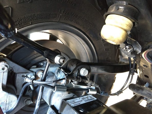
Re-clip the wheel speed senor wire to the axle side brake line retention bracket, and zip tie the sensor wire to the brake line in the appropriate locations to prevent damaging the speed sensor wire at full droop.
-
Using a 13mm wrench/socket torque the axle side brake line retention bracket bolt to 8 lb-ft [11 Nm]
-
-
-
Repeat for the other side.
-
Bleed the brakes according to the Factory Service Manual.
-


![Using a 13mm wrench/socket torque the axle side brake line retention bracket bolt to 8 lb-ft [11 Nm]](https://d3t0tbmlie281e.cloudfront.net/igi/grimmoffroad/fFKkUFNR14ZbKGQB.medium)
Installation is complete!
With any modified vehicle, or any vehicle used offroad, it is a good idea to check bolt torques periodically and visually inspect components regularly.
Installation is complete!
With any modified vehicle, or any vehicle used offroad, it is a good idea to check bolt torques periodically and visually inspect components regularly.
