
Introduction
This guide will walk through the correct installation procedure for the Grimm OffRoad JL Hardware Upgrade Kit.
Consumer Warning
All Grimm OffRoad products must be installed by a competent and qualified individual in accordance with the installation instructions intended for the product. Incorrectly installed products will void any warranties and may result in damage to the product or damage to the vehicle it was installed on. Read any provided instructions or guides and watch any available videos before attempting installation. If there are any questions, please contact Grimm OffRoad before starting installation.
Many products require the vehicle be properly raised and supported off the ground. The installer is responsible for confirming that this may be done in a safe manner and the correct equipment is available to perform the installation. Grimm OffRoad installation instructions assume the installer is able to properly and safely lift the vehicle.
Vehicles that have been modified will not perform the same as a stock vehicle. It is incumbent upon the owner of the vehicle to be aware of the differences the modifications will make to the driving characteristics of the vehicle. These may include (but are not limited to): changes in handling, braking, rollover angle, incompatibilities with the factory anti-lock braking systems, stability control systems, or traction control systems.
Tools
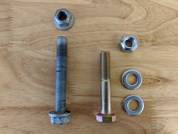
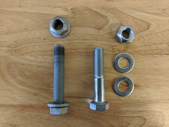
Parts
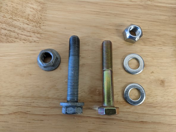
- M16-1.5 x 100mm Grade 10.9 Hex Head Bolt × 4
- M14-1.5 x 70mm Grade 10.9 Hex Head Bolt × 4
- M14-1.5 x 100mm Grade 10.9 Hex Head Bolt × 8
- M12-1.5 x 80mm Grade 10.9 Hex Head Bolt × 4
- M12-1.5 x 70mm Grade 10.9 Hex Head Bolt × 4
- M12 Flat Washer × 14
- M14 Flat Washer × 18
- M16 Flat Washer × 8
- M12-1.5 Hex Lock Nut × 6
- M14-1.5 Hex Lock Nut × 6
- M16-1.5 Hex Lock Nut × 4
Video Overview
-
-
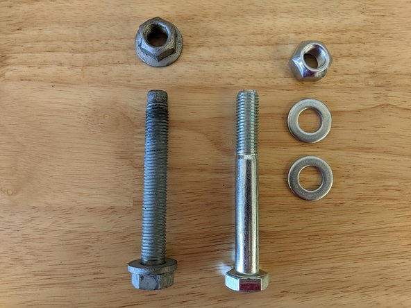
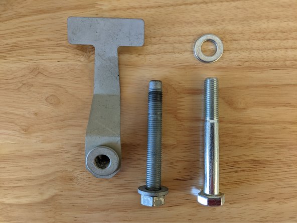
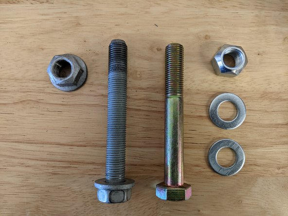
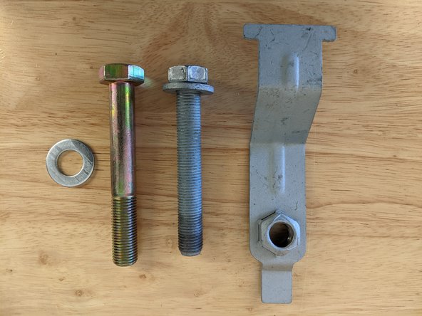
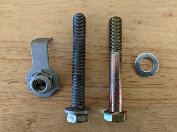
Verify that all parts shown in the picture are present.
-
This hardware kit should be installed with the vehicle on the ground resting on its own weight. It is not recommended to be done on a vehicle lift as the Jeep's suspension should be at ride height when all of the hardware is torqued.
-
Placing the front and rear axles on jack stands will give you more room to work and you can also remove the wheels/tires if desired.
-
When replacing the stock hardware with the hardware included in this kit, changing one piece at a time will make the job easier by keeping the axles in alignment.
-
If any bolts do not line up or are difficult to get in, a ratchet strap may be used to pull the components back into alignment. If you left the wheels and tires on and the vehicle is sitting on the ground, having a helper turn the steering wheel can help align the components.
-
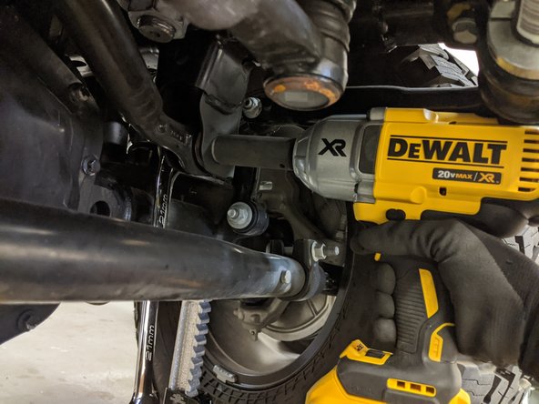
An impact wrench will make this job easier, but a breaker bar can be used as well.
-
-
-
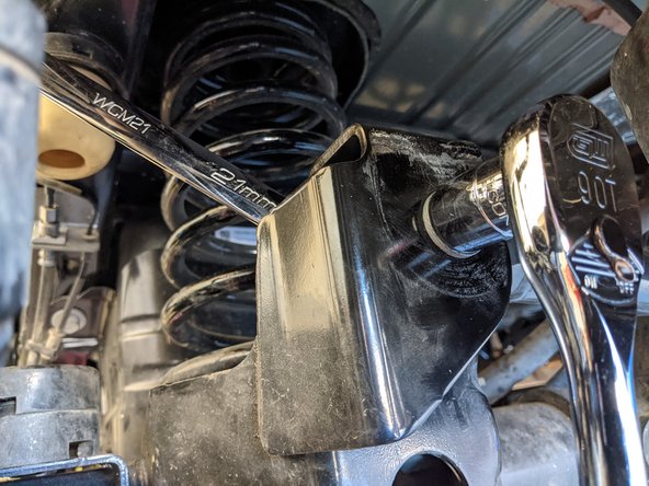
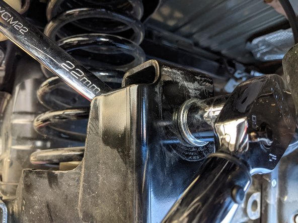
Start with the front lower control arms.
-
The stock bolts for the front lower control arms are 21mm for the bolt head and 24mm for the nut.
-
Remove one bolt at a time and replace with an M16-1.5 x 100mm bolt and lock nut with washers under the head of the bolt and lock nut.
-
If you have trouble getting the new bolts in, a ratchet strap can be used to help pull the axle back into alignment.
-
Torque with a 24mm wrench/socket to 215 lb-ft [295 Nm].
-
Repeat for all four bolts on both front lower control arms.
-
-
-
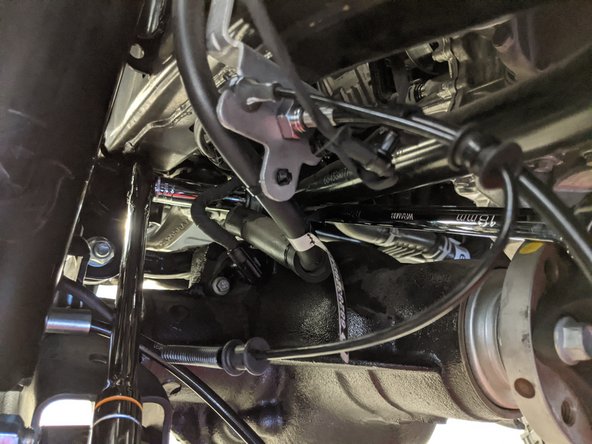
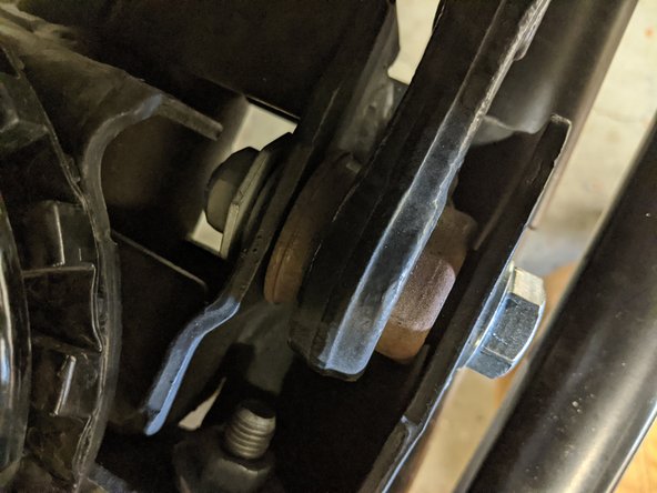
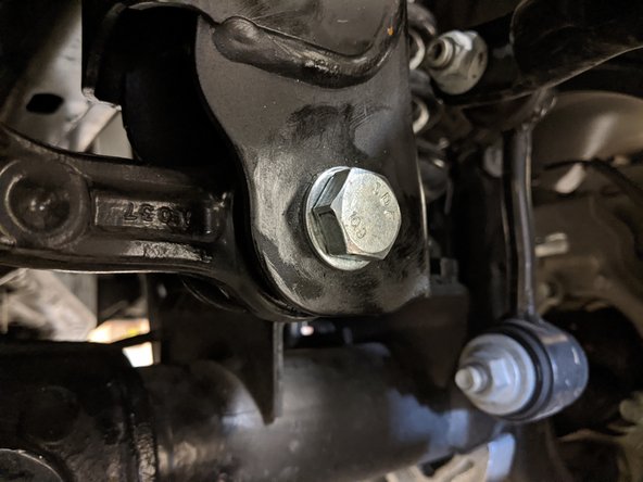
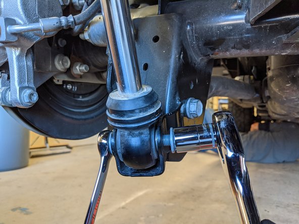
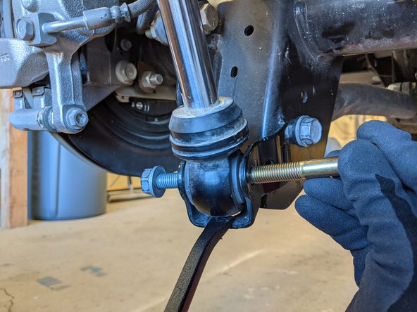
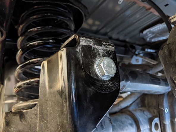
Move onto the front lower shock mounts
-
With an 18mm wrench/socket, loosen the stock bolts and nuts but do not remove yet.
-
The lower eyelet of the shock will need to be supported before removing the shock bolt to prevent the shock from extending and coming out of the mount. With Nitrogen charged shocks it can be very difficult to get the shock back into the mount.
-
Grab one of the M12-1.5 x 70mm bolts and put a washer on it. Using your pry bar, support the lower shock eyelet so you can easily slide the stock bolt out. Once out, slide the new bolt with washer into the mount and then ease off the pry bar. Add another washer and lock nut.
-
Torque with a 19mm wrench/socket to 90 lb-ft [120 Nm]
-
Repeat for both front lower shock mounts.
-
-
-
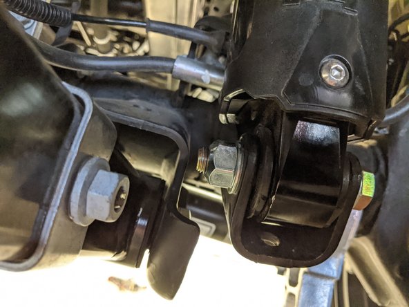
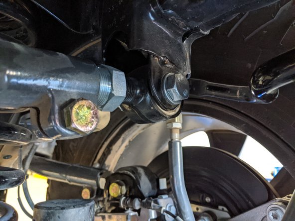
Move onto the front upper control arm axle side hardware.
-
The stock bolts and nuts for the front upper control arms are 18mm.
-
Remove one bolt at a time and replace with an M12-1.5 x 80mm bolt and lock nut with washers under the head of the bolt and lock nut.
-
If you have trouble getting the new bolt in, a ratchet strap can be used to help pull the axle back into alignment.
-
Torque with a 19mm wrench/socket to 90 lb-ft [120 Nm]
-
Repeat for both front upper control arm axle side bolts.
-
-
-
Move onto the front upper control arm frame side hardware.
-
Remove the two screws holding on the heat shield with a 10mm wrench/socket and remove the heat shield.
-
Repeat for both front upper control arm frame side heat shields.
-
-
-
The stock bolts for the front upper control arms use an 18mm wrench/socket.
-
Remove one bolt at a time and replace with an M12-1.5 x 80mm bolt and washer, reusing the stock flag nut.
-
If you have trouble getting the new bolt in, a ratchet strap can be used to help pull the axle back into alignment.
-
Torque with a 19mm wrench/socket to 90 lb-ft [120 Nm]
-
Reinstall the heat shield with a 10mm wrench/socket and torque to 40 lb-in [4.5 Nm] (Note, this is pounds per inch, not foot! Don't overtighten!)
-
Repeat for both front upper control arm frame side bolts and heat shields.
-
-
-
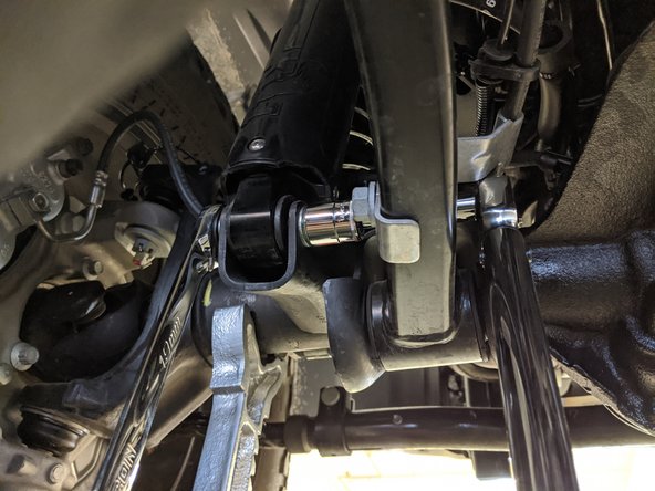
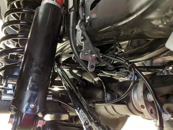
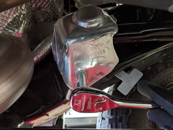
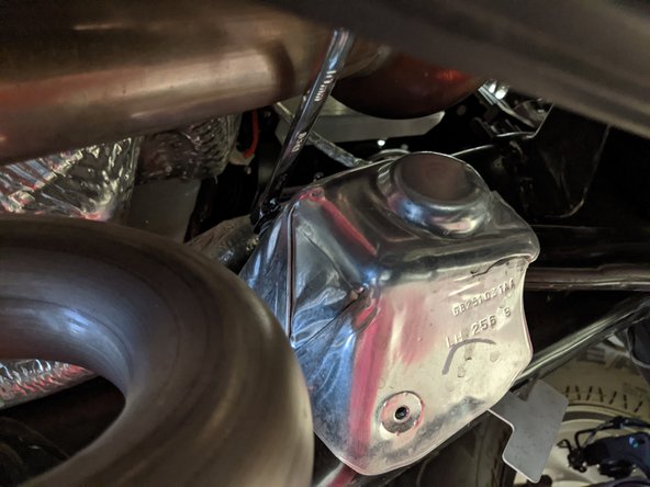
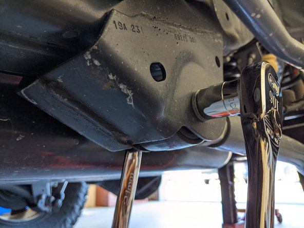
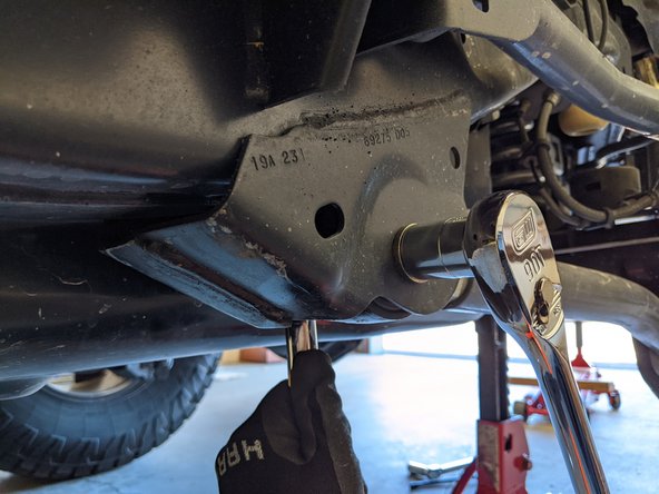
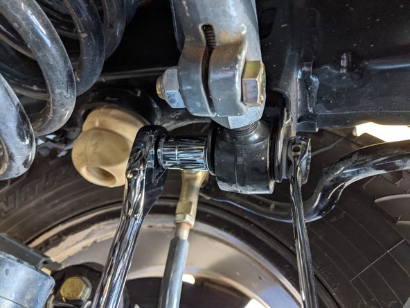
Move onto the front axle side track bar mount
-
Remove the front axle side track bar bolt with a 21mm wrench/socket.
-
Replace with an M14-1.5 x 70mm bolt and washer, reusing the stock flag nut.
-
If you have trouble getting the new bolt in, simultaneously pulling the front bumper towards the driver side will release tension on the bolt making it easier to get in.
-
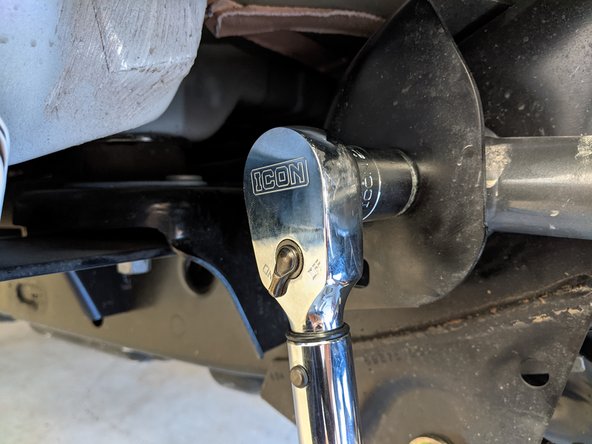
Torque with a 22mm wrench/socket to 135 lb-ft [185 Nm].
-
-
-
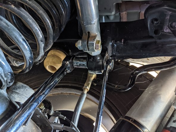
Move onto the front frame side track bar mount
-
Remove the front frame side track bar bolt and nut with a 21mm wrench/socket.
-
Make sure to hold onto the track bar so it doesn't drop out of the bracket.
-
Replace with an M14-1.5 x 70mm bolt and lock nut with washers under the head of the bolt and lock nut.
-
If you have trouble getting the new bolt in, simultaneously pulling the front bumper towards the driver side will release tension on the bolt making it easier to get in.
-
Torque with a 22mm wrench/socket to 135 lb-ft [185 Nm].
-
-
-
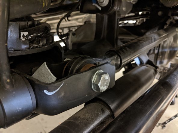
Move onto the rear lower shock mounts
-
With an 18mm wrench/socket, loosen the stock bolts and nuts but do not remove yet.
-
The lower eyelet of the shock will need to be supported before removing the shock bolt to prevent the shock from extending and coming out of the mount. With Nitrogen charged shocks it can be very difficult to get the shock back into the mount.
-
Grab one of the M12-1.5 x 70mm bolts and put a washer on it. Using your pry bar, support the lower shock eyelet and slide the new bolt in from the opposite direction, pushing the stock bolt out. Add another washer and lock nut.
-
Pushing the bolt in from the opposite direction will cause the exposed threads of the bolt to face the wheel and be more protected from rock rash or damage.
-
Torque with a 19mm wrench/socket to 90 lb-ft [120 Nm]
-
Repeat for both rear lower shock mounts.
-
-
-
Move onto the rear lower control arms.
-
The stock bolts for the rear lower control arms are 21mm.
-
Remove one bolt at a time and replace with an M14-1.5 x 100mm bolt and lock nut with washers under the head of the bolt and lock nut.
-
On the axle side bolts, make sure to insert the new bolts from the inside, towards the wheel. This will cause the exposed threads of the bolt to face the wheel and be more protected from rock rash or damage.
-
If you have trouble getting the new bolts in, a ratchet strap can be used to help pull the axle back into alignment.
-
Torque with a 22mm wrench/socket to 135 lb-ft [185 Nm].
-
Repeat for all four bolts on both rear lower control arms.
-
-
-
Move onto the rear upper control arms
-
The stock bolts for the rear upper control arms are 21mm.
-
Remove one bolt at a time and replace with an M14-1.5 x 100mm bolt and washer, reusing the stock flag nut.
-
If you have trouble getting the new bolts in, a ratchet strap can be used to help pull the axle back into alignment.
-
Torque with a 22mm wrench/socket to 135 lb-ft [185 Nm].
-
Repeat for all four bolts on both rear upper control arms.
-
It is helpful to remove the rear wheels when replacing the axle side upper control arm bolts.
-
-
-
Move onto the rear axle side track bar mount
-
Remove the rear axle side track bar bolt with a 21mm socket/wrench.
-
Make sure to hold onto the track bar so it doesn't drop out of the bracket.
-
Replace with an M14-1.5 x 70mm bolt and washer, reusing the stock flag nut.
-
If you have trouble getting the new bolt in, simultaneously pulling the frame towards the passenger side will release tension on the bolt making it easier to get in.
-
Torque with a 22mm wrench/socket to 135 lb-ft [185 Nm].
-
-
-
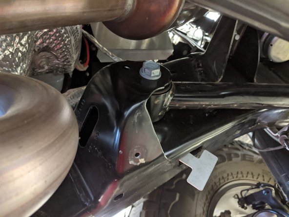
Move onto the rear axle side track bar mount
-
Remove the rear frame side track bar bolt and nut with a 21mm .
-
Make sure to hold onto the track bar so it doesn't drop out of the bracket.
-
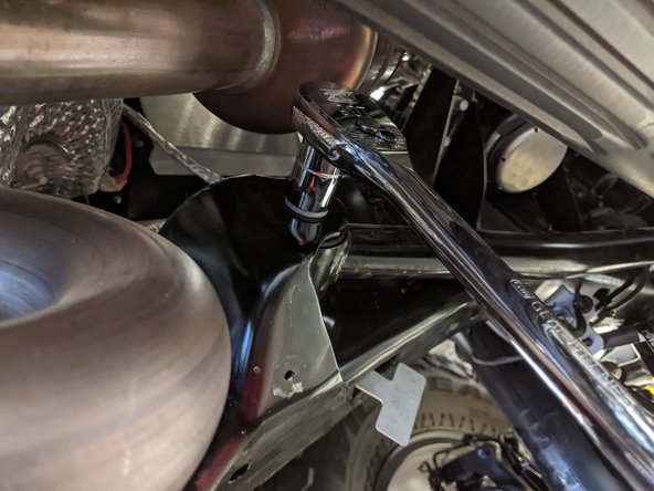
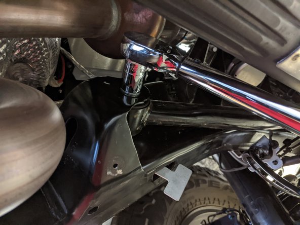
Replace with an M14-1.5 x 70mm bolt and lock nut with washers under the head of the bolt and lock nut.
-
If you have trouble getting the new bolt in, simultaneously pulling the frame towards the passenger side will release tension on the bolt making it easier to get in.
-
Torque with a 22mm wrench/socket to 135 lb-ft [185 Nm].
-


Installation is complete!
With any modified vehicle, or any vehicle used offroad, it is a good idea to check bolt torques periodically and visually inspect components regularly.
Because the track bar bolts were replaced and the track bars have the possibility of shifting slightly in their mounting holes, the steering wheel may no longer be centered. Adjust the length of the drag link as needed to center the steering wheel.
