Introduction
This guide will walk through the correct installation procedure for the Grimm OffRoad F-150 2.3 Inch Leveling Spacer Kit.
Consumer Warning
All Grimm OffRoad products must be installed by a competent and qualified individual in accordance with the installation instructions intended for the product. Incorrectly installed products will void any warranties and may result in damage to the product or damage to the vehicle it was installed on. Read any provided instructions or guides and watch any available videos before attempting installation. If there are any questions, please contact Grimm OffRoad before starting installation.
Many products require the vehicle be properly raised and supported off the ground. The installer is responsible for confirming that this may be done in a safe manner and the correct equipment is available to perform the installation. Grimm OffRoad installation instructions assume the installer is able to properly and safely lift the vehicle.
Vehicles that have been modified will not perform the same as a stock vehicle. It is incumbent upon the owner of the vehicle to be aware of the differences the modifications will make to the driving characteristics of the vehicle. These may include (but are not limited to): changes in handling, braking, rollover angle, incompatibilities with the factory anti-lock braking systems, stability control systems, or traction control systems.
Notes
- This leveling spacer kit will change the alignment of your vehicle. An aftermarket alignment Caster/Camber Kit is not required but is recommended to help correct the alignment. It is important that when the vehicle is taken to be aligned that the alignment technician is familiar with modified vehicles and does not simply try to match the factory alignment settings.
Tools
-
-
Verify all parts are present.
-
-
-
Park the vehicle on a flat, level surface. Make sure the vehicle is in park or in gear, and that the parking brake is set. Raise the front of the vehicle and support the frame with jackstands.
-
Remove front wheels with a 21mm socket/wrench.
-
Both sides of the vehicle need to be jacked up and supported with jack stands at the same time, as the vehicle's struts will be getting swapped from side to side during this install.
-
-
-
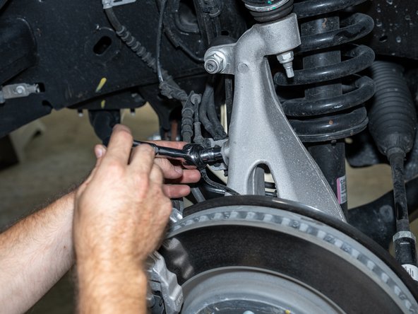
Using a 10mm socket/wrench, remove the brake line/ABS bracket from the knuckle.
-
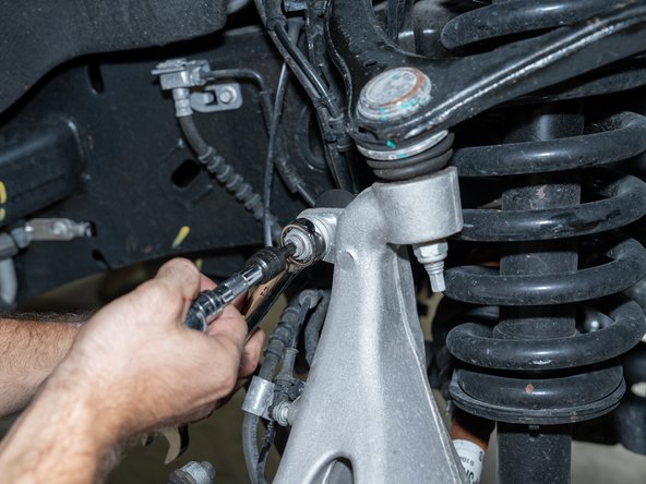
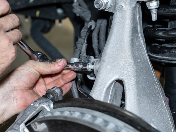
Using a 21mm wrench and T45 Torx driver, disconnect the sway bar link from the knuckle.
-
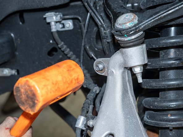
A mallet may be needed to help push the sway bar link stud out of the knuckle.
-
-
-
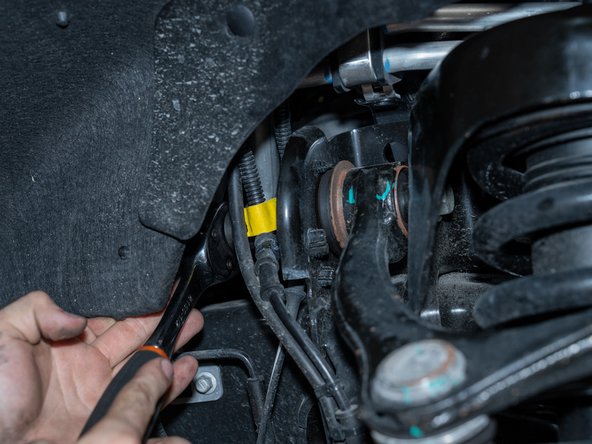
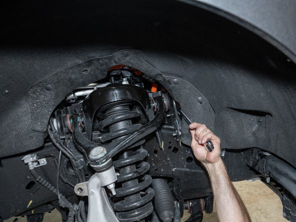
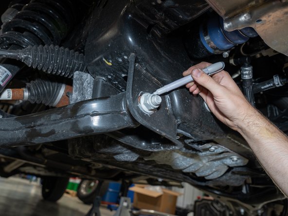
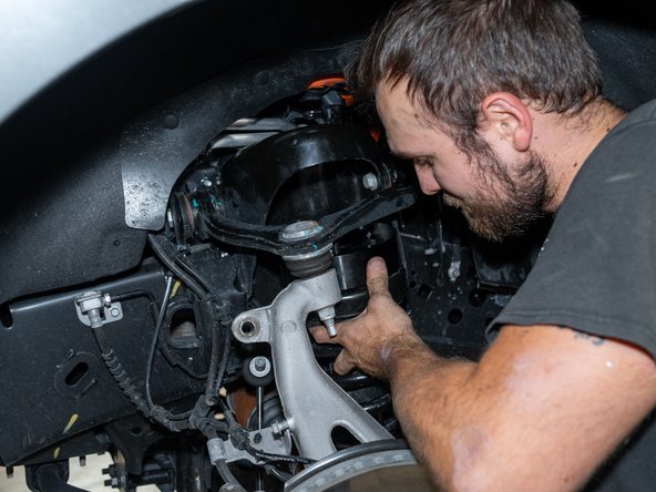
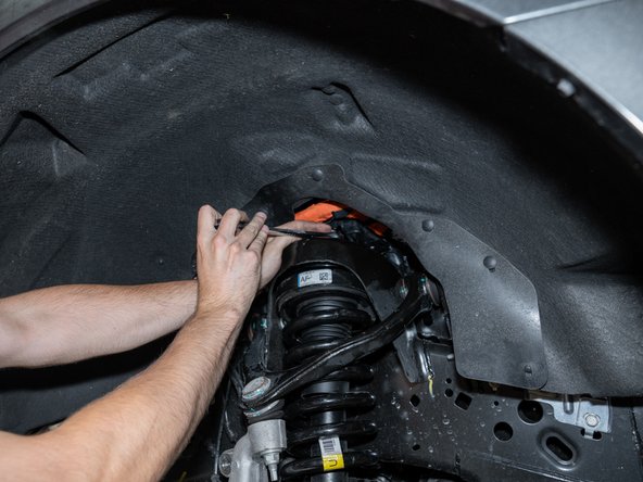
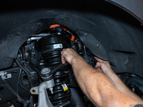
Using a 21mm socket/wrench, loosen the upper control arm bolts. Just loosen, do not remove.
-
-
-
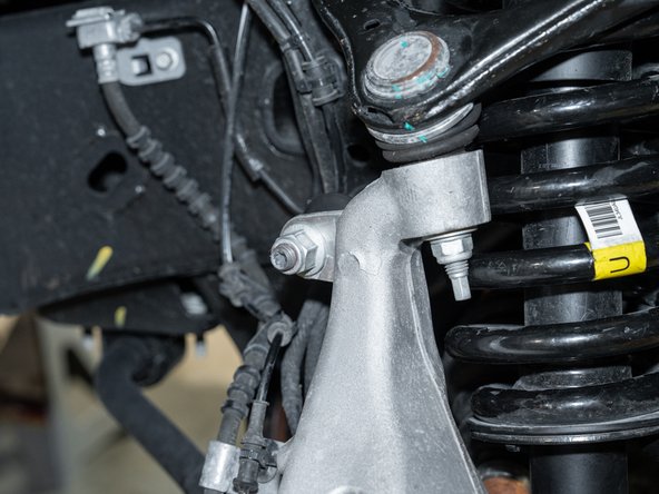
Remove the nuts from the lower strut mounting studs with an 18mm socket/wrench.
-
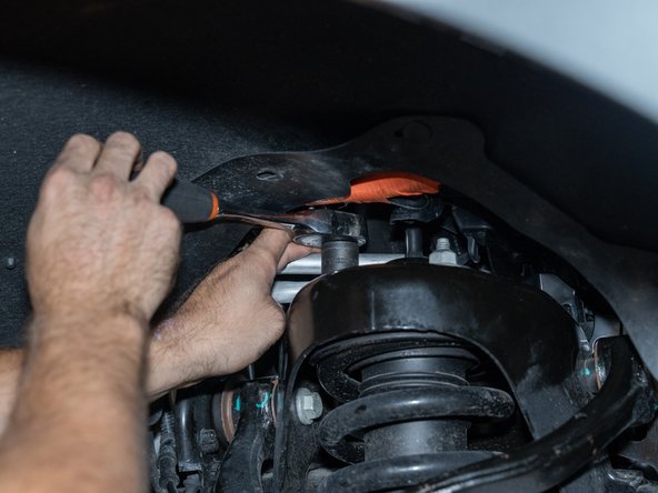
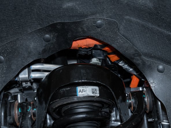
Remove the nuts from the upper strut mounting studs with an 18mm socket/wrench.
-
-
-
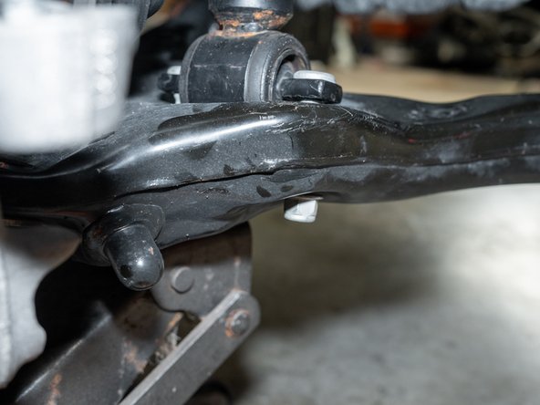
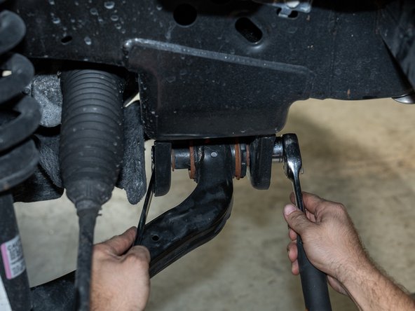
Mark the lower control arm bolt position before removing to make sure they are reinstalled in the same position.
-
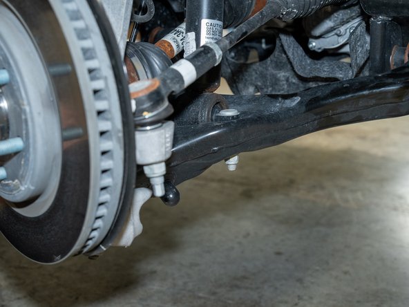
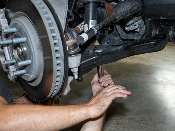
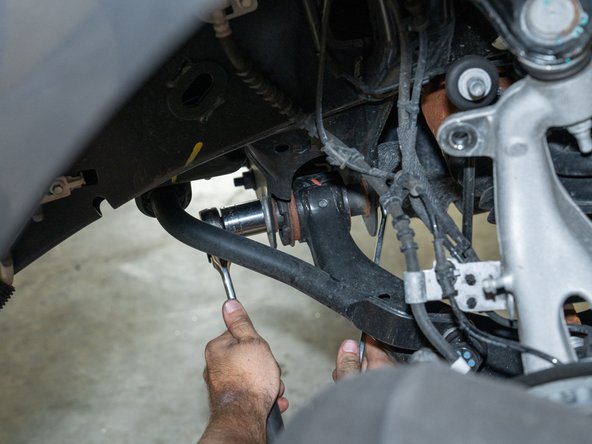
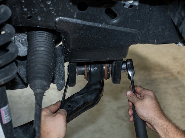
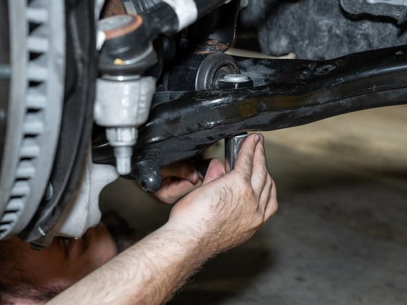
Remove the lower control arm bolts using a 27mm socket/wrench and a 21mm wrench.
-
A breaker bar may be needed to help break these bolts loose.
-
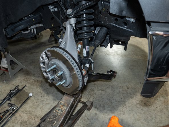
It is helpful to support the knuckle/hub assembly with a floor jack when removing these bolts to prevent damage to any of the front end components.
-
-
-
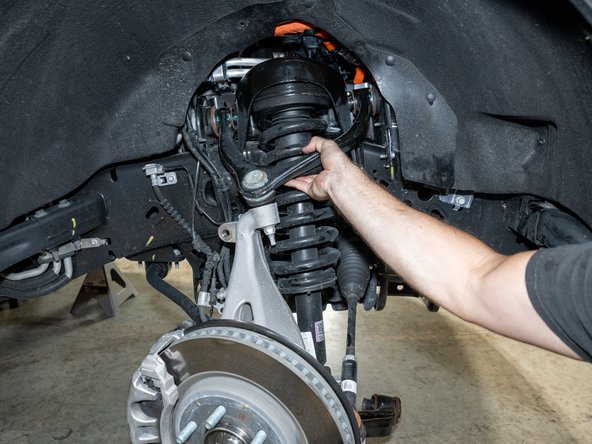
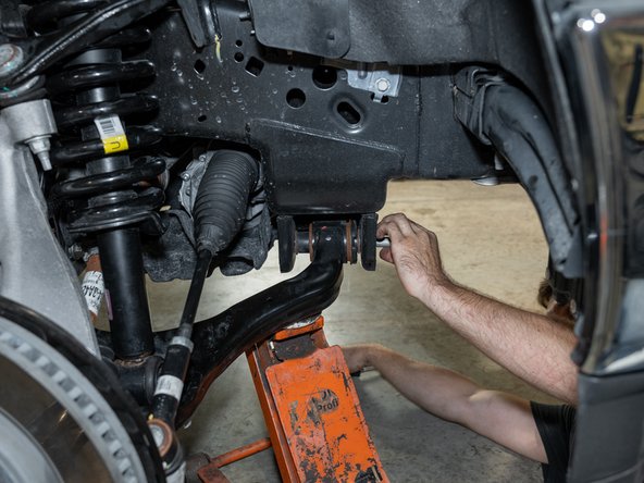
Drop the lower control arm out of its frame brackets and pull the strut out of the vehicle.
-
Make note of the left and right struts, as they will need to switch sides when reassembling everything.
-
If there are issues getting the struts out, it may be easier to also disconnect the tie rod end links at the knuckle. If doing so, after loosening the nut, striking the knuckle with a hammer will be necessary to help break the taper free.
-
-
-
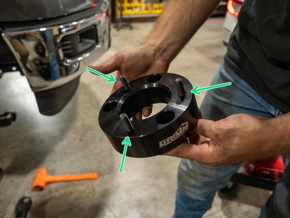
With the provided socket cap screws, install into the Grimm OffRoad spacers from the bottom.
-
Torque the socket cap screws with an 8mm hex driver to 54 lb-ft (73 Nm).
-
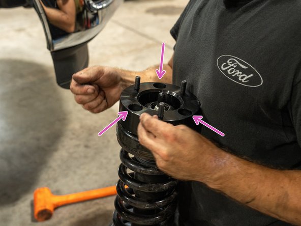
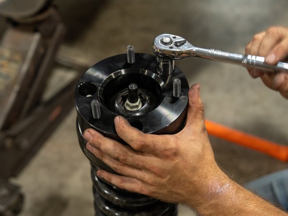
Next, bolt the Grimm OffRoad spacers to the factory strut assemblies using the provided washers and nylock nuts.
-
Note that the 3-bolt pattern is offset and they will only install one way.
-
Torque with a 17mm socket to 54 lb-ft (73 Nm).
-
-
-
Reinstall struts making sure to swap the struts from side to side. Left strut should be installed on the right side of the vehicle and right strut on the left side of the vehicle. This ensures the strut bushings are not bound up and wear prematurely.
-
Note that the 3-bolt pattern on the top of the struts is offset and they will only install one way.
-
Use the factory hardware to secure the top of the struts, but do not yet tighten.
-
Reinstall the stock hardware to secure the bottom of the strut but do not yet tighten.
-
-
-
Reconnect lower control arms by using a floor jack to help push the arms into position.
-
If an aftermarket alignment Caster/Camber Kit is being installed, install it now.
-
Reinstall bolts but do not yet tighten.
-
An alignment bar can be very helpful for getting the lower control arm bolts lined up and reinstalled.
-
Torque nuts on top of strut with an 18mm socket to 50 lb-ft (68 Nm).
-
Torque nuts on bottom of strut with an 18mm socket to 66 lb-ft (90 Nm).
-
-
-
Reconnect upper sway bar link to knuckle.
-
Torque sway bar link nut with an 18mm socket to 55 lb-ft (74 Nm)
-
Using a 10mm socket/wrench, torque the brake line/ABS bracket to 16 lb-ft (22 Nm)
-
If the tie rod end links were disconnected earlier, reinstall them now and torque to 85 lb-ft (115 Nm).
-
-
-
Upper and lower control arm bolts should be installed but still loose at this point. They need to be torqued only when the truck is under it's own weight.
-
If the install is being done on floor jacks, it is near impossible to tighten the control arm bolts with the wheels on while lining up the lower control arm alignment marks from earlier.
-
We suggest placing the floor jack under the control arm and lift until the suspension compresses just enough to become light on the jack stand. This will get you close enough to ride height to tighten the control arm bolts.
-
A pry bar will help align the lower control arm bolts to the alignment marks made earlier. Get it as close as you can, it doesn't have to be perfect. it is likely to change once it gets professionally aligned due to the increased ride height.
-
Torque upper control arm bolts to 122 lb-ft (165 Nm)
-
Torque lower control arm bolts to 258 lb-ft (350 Nm)
-
-
-
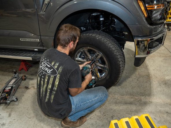
Reinstall wheels and torque lug nuts to 150 lb-ft (203 Nm).
-
Remove jack stands and lower truck.
-
-
-
Have vehicle professionally aligned.
-
Re-check all bolt torques after the first 100 miles, and after every trip offroad.
-
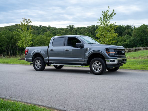
Installation is Complete!
Installation is Complete!
