
Introduction
This guide will walk through the correct installation procedure for the Grimm OffRoad Ford Bronco ARB Twin Compressor Bracket. When the ARB Twin Compressor is in use, it is always recommended to leave the engine running.
Consumer Warning
All Grimm OffRoad products must be installed by a competent and qualified individual in accordance with the installation instructions intended for the product. Incorrectly installed products will void any warranties and may result in damage to the product or damage to the vehicle it was installed on. Read any provided instructions or guides and watch any available videos before attempting installation. If there are any questions, please contact Grimm OffRoad before starting installation.
Many products require the vehicle be properly raised and supported off the ground. The installer is responsible for confirming that this may be done in a safe manner and the correct equipment is available to perform the installation. Grimm OffRoad installation instructions assume the installer is able to properly and safely lift the vehicle.
Vehicles that have been modified will not perform the same as a stock vehicle. It is incumbent upon the owner of the vehicle to be aware of the differences the modifications will make to the driving characteristics of the vehicle. These may include (but are not limited to): changes in handling, braking, rollover angle, incompatibilities with the factory anti-lock braking systems, stability control systems, or traction control systems.
Supporting Parts
This Grimm OffRoad product is designed to be used in conjunction with an ARB Twin Compressor (Specifically the CKMTA12 ). It is important to review and familiarize yourself with the instructions provided with the compressor before beginning installation.
We recommend also pairing with ARB’s 171302 Pump Up Kit which includes the required air hose coupling and fill up hose. Alternatively, ARB’s 0740112 air hose coupling or similar can be used.
Tools
Parts
- Main Bracket
- PCM Mounting Bracket Assembly
- Support Bracket
- Side Support Bracket
- JIC4 Fitting (90 degree)
- JIC4 Fitting (Straight)
- Control Harness
- High Pressure Stainless Steel Air Line
- M6x1.0 20mm Carriage Bolt × 8
- M6x1.0 25mm Carriage Bolt
- M6x1.0 Nylock Flange Nut × 11
- 1/4" Flat Washer × 11
- M6x1.0 Vibration Damping Bushing
- Zip Tie × 4
- ARB Twin Air Compressor Part CKMTA12 (Required)
- Ring Terminal, 6ga, M8 Stud Size (Required) × 3
- ARB 0740110 90 Degree JIC4 Fitting (Optional for mounting ARB Manifold ARB171503)
Video Overview
-
-
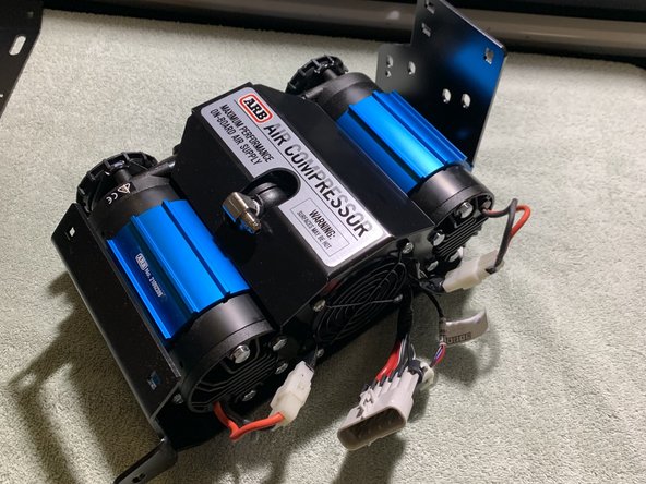
Verify that all parts shown in the pictures are present.
-
Three 6 gauge M8 stud size ring terminals are required to connect the ARB Twin Compressor to the vehicle's battery.
-
-
-
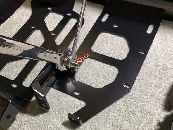
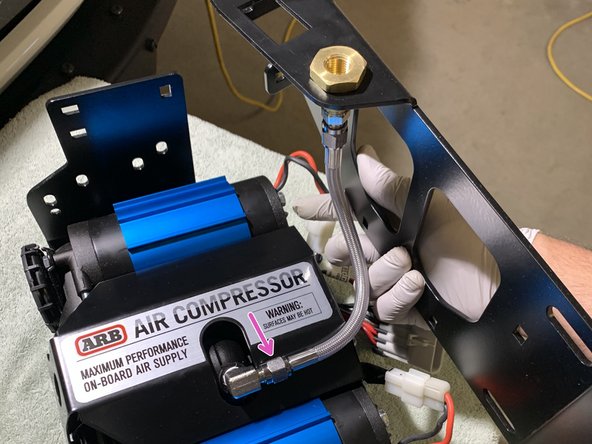
Install the 1/4” NPT x JIC4 90° fitting into the ARB compressor manifold cap using a 9/16" open end wrench. Make sure to use thread sealant on the NPT thread and orient the fitting as shown.
-
To optimize air line route, loosen manifold cap with 10mm box end wrench and rotate housing 15deg. Once adjusted, tighten manifold cap to approximately 7 lb-ft (9 Nm)
-
Note that NPT fittings are tapered fittings and must not be overtightened. If you can't get the fittings to point the correct direction, it is recommended to remove, use a couple additional wraps of Teflon tape, then reinstall.
-
-
-
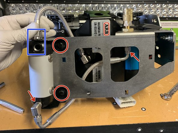
Install the straight 1/4” NPT x JIC4 fitting into the back of the bulkhead fitting on the PCM Mounting Bracket Assembly using a 9/16" open end wrench. Use thread sealant on the NPT threads.
-
Note that NPT fittings are tapered fittings and must not be overtightened.
-
Note that a 1" open end wrench can be used on the opposite side to prevent the bulkhead fitting from spinning while installing the NPT fitting.
-
-
-
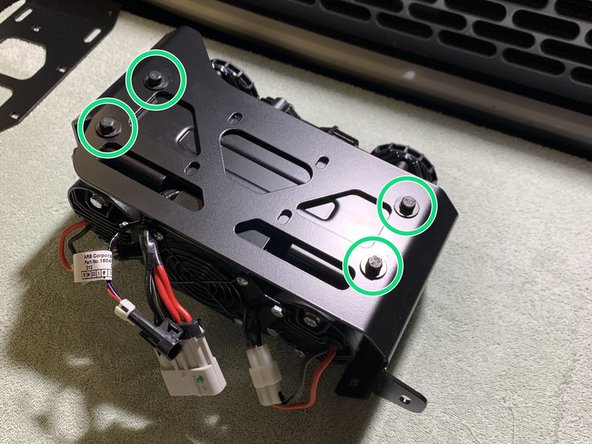
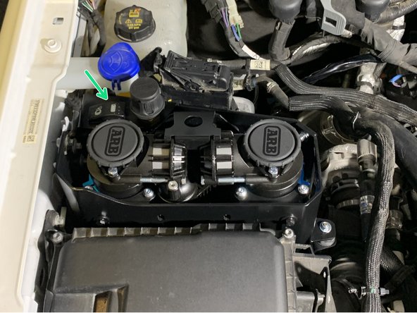
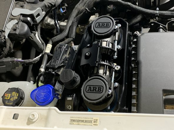
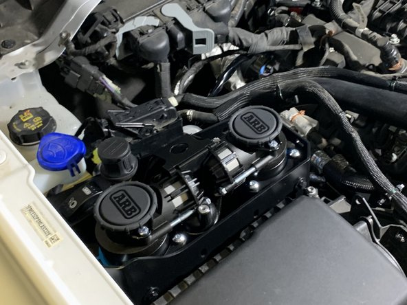
With the mounting holes of the ARB Twin compressor facing up, set the Grimm OffRoad Main Bracket into the Compressor oriented as shown.
-
Secure the compressor onto the Grimm Offroad Main Bracket using the ARB supplied 6mm hardware with a 10mm socket/wrench.
-
Torque mounting hardware to 7 lb-ft [9 Nm].
-
-
-
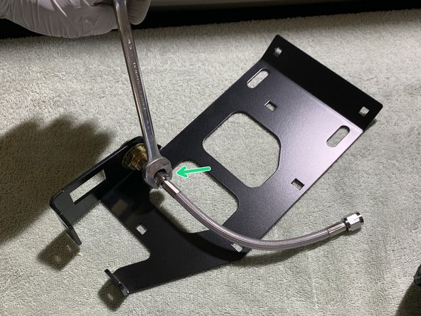
Install one end of the included Stainless Steel Pressure Hose on to the previously installed NPT fitting on the PCM Mounting Bracket Assembly using a 9/16" open end wrench.
-
Install the other end of the included Stainless Steel Pressure Hose on to the previously installed NPT fitting on the compressor.
-
The Stainless Steel Pressure Hose uses flared fittings and thread sealant is not required.
-
Orient the PCM Mounting Bracket Assembly as shown when tightening the Stainless Steel Pressure Hose.
-
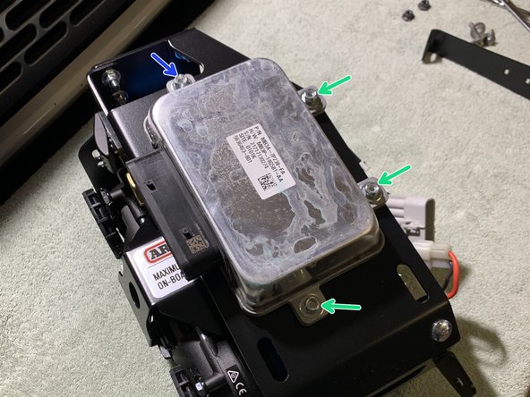
Note that if you are installing the ARB Manifold Kit (171503), take steps to install airlines and manifold at this time. Note: An additional 1/4 NPT - JIC4 90 degree fitting (ARB 0740110) will be required for installation. (Blue Square)
-
-
-
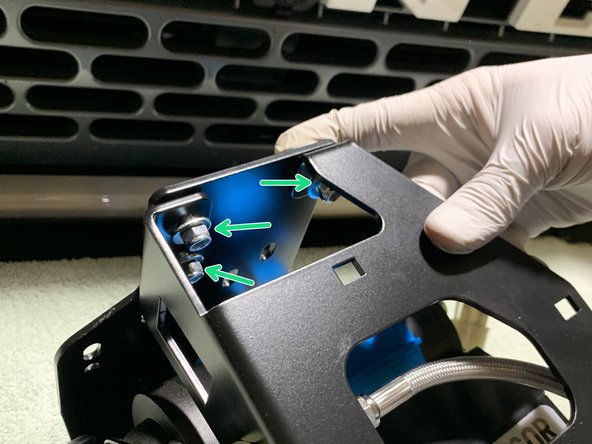
Assemble the Main Bracket and PCM Mounting Bracket Assembly together as shown using the five M6x1.0 20mm Carriage Bolts with a washer under the nylock nut using a 10mm socket/wrench.
-
Torque carriage bolt hardware to 7 lb-ft [9 Nm].
-
-
-
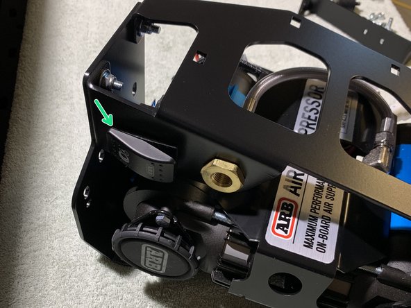
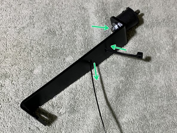
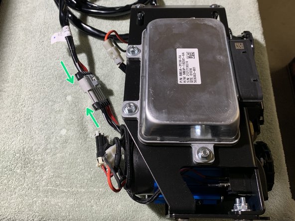
Be absolutely sure that you hook up this switch correctly according to the diagram in the first image. If wired incorrectly, you can short power directly to ground and damage the wiring in the compressor itself. ARB will not warranty your compressor if this happens.
-
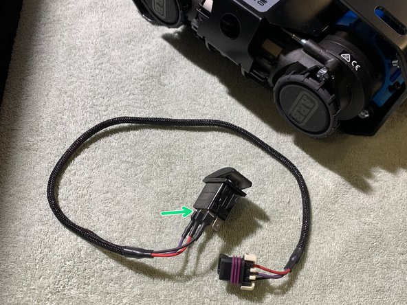
Plug the wires into the back of the ARB compressor switch. The BLACK wire goes to the top terminal, the RED wire goes to the center terminal and the PURPLE wire goes to the lower terminal.
-
Route the Grimm OffRoad Control Harness through the switch hole in the Controls Plate.
-
To install the switch, push the switch into the Controls Plate until it snaps into place.
-
Note that you can install the air hose coupling into the bulkhead fitting at this time. We recommend using ARB's 0740112 Air Hose Coupling which is included in their 171302 Pump Up Kit.
-
-
-
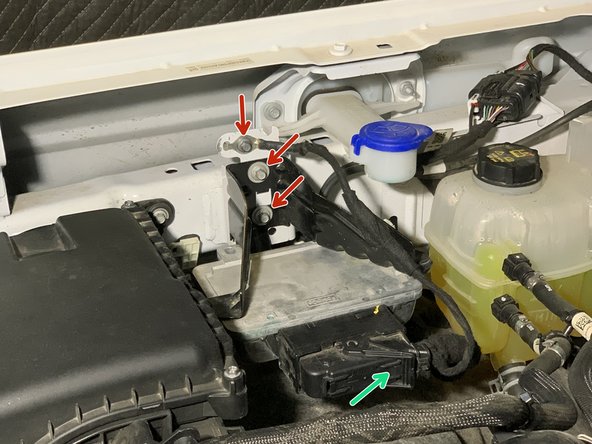
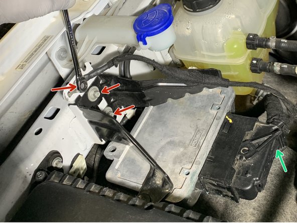
Loosen and remove the 3 bolts holding the ground wire and PCM Mounting Bracket to the vehicle using an 8mm socket/wrench.
-
Unplug the PCM unit and install PCM onto the PCM Mounting Bracket Assembly using three of the provided M6x1.0 20mm Carriage Bolts using a washer under the nylock nuts with a 10mm socket/wrench.
-
Loosely install one M6x1.0 25mm Carriage Bolt using a washer under the nylock nut. The PCM Side Support Bracket will install onto the M6x1.0 25mm Carriage Bolt once the compressor is mounted in place.
-
Torque 20mm long carriage bolt hardware to 7 lb-ft [9 Nm].
-
-
-
Install the 6mm x 1" vibration damping bushing onto the Support Bracket using a washer under the 6mm nylock nut as shown.
-
Use a 10mm socket/wrench to torque the nut to 7 lb-ft [9 Nm].
-
Thread one of the provided zip ties through the Support Bracket as shown.
-
The next steps differ depending on what engine configuration you have. Follow Step 10 for the 2.7L engine and Steps 11-14 for the 2.3L engine.
-
-
-
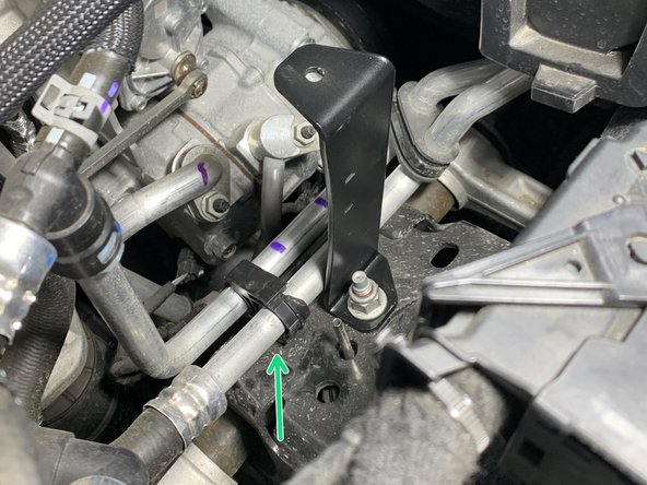
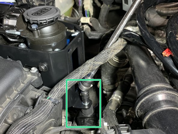
Using a 15mm socket, remove the upper shock tower mounting nut and install the support bracket as shown using factory flange nut.
-
Use a 15mm socket/wrench to torque the nut to 51 lb-ft [64 Nm].
-
Secure the coolant hose to the Support Bracket as shown with the zip tie installed earlier.
-
-
-
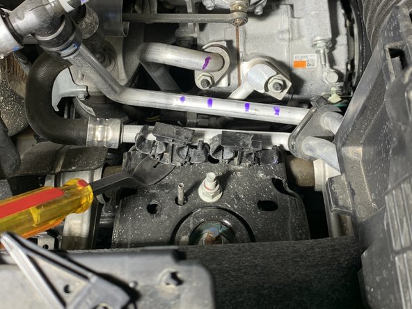
This step only applies to the 2.3L engine.
-
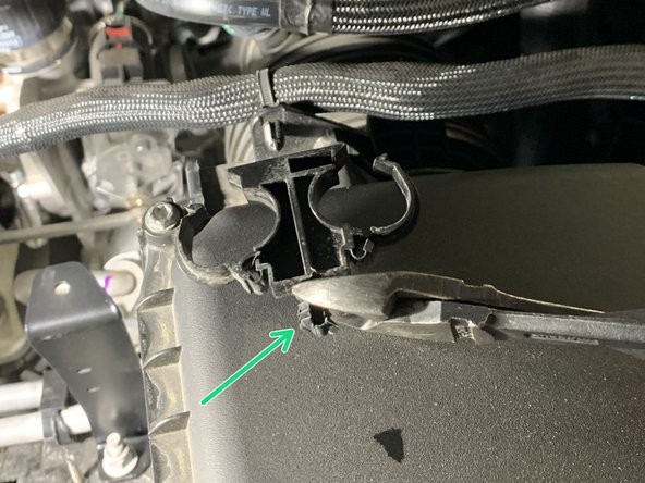
Use a flat head screw driver to open the coolant line clips as shown.
-
Separate the clips from the coolant lines.
-
Remove the clips from the shock tower using a vehicle trim tool or similar.
-
-
-
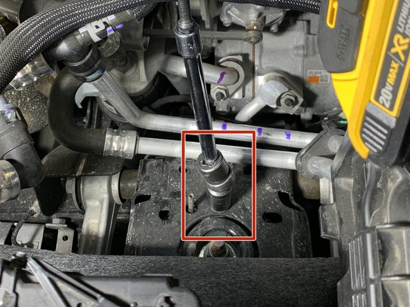
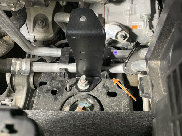
Using a 15mm socket, remove the upper shock tower mounting nut and install the support bracket as shown using factory flange nut.
-
Use a 15mm socket/wrench to torque the nut to 51 lb-ft [64 Nm].
-
-
-
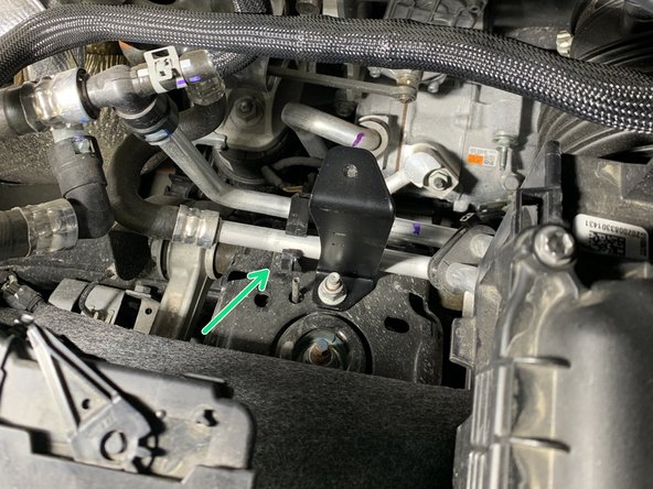
Reinstall the left coolant line clip onto the coolant lines and insert the christmas tree clip end on the bottom back into the hole in the shock tower where it was removed from.
-
-
-
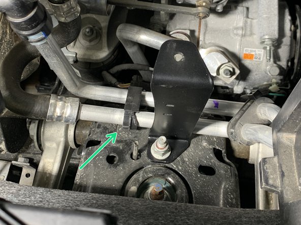
The right clip needs the christmas tree end removed before reinstalling. Cut flush with diagonal cutters.
-
Reinstall clip back onto the coolant lines on the right side of the installed support bracket.
-
If rubbing looks like it could be a concern, a zip tie can be installed here to prevent the coolant line from contacting the support bracket.
-
Overall the coolant lines don’t have much movement since the hard line is attached to a grommet which is holding the coolant bypass valve.
-
-
-
Connect the ARB Power Harness to the ARB Twin Compressor.
-
-
-
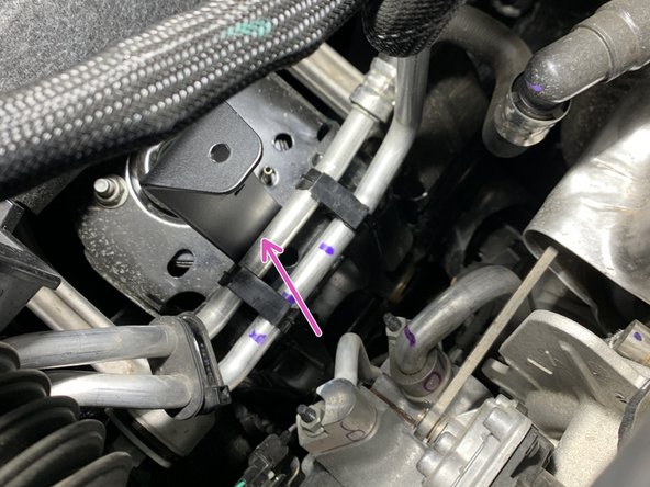
Install the compressor assembly onto the vibration damping bushing, sandwiching it between the Support Bracket and Main Bracket using a washer under a 6mm nylock nut as shown.
-
Use a 10mm socket/wrench to torque hardware to 7 lb-ft [9 Nm].
-
Do not use an impact wrench; doing so may cause damage to the bushing.
-
Reuse the 8mm PCM Mounting Bracket bolts to secure the compressor assembly to the same location the PCM Mounting Bracket was removed from. Make sure to reattach the ground cable in the top mounting hole.
-
Reconnect the PCM wire harness.
-
Use a 8mm wrench to torque hardware to approximately 21 lb-ft [28 Nm].
-
-
-
Remove the 6mm nylock nut & washer from the M6x1.0 25mm Carriage Bolt previously installed on the PCM.
-
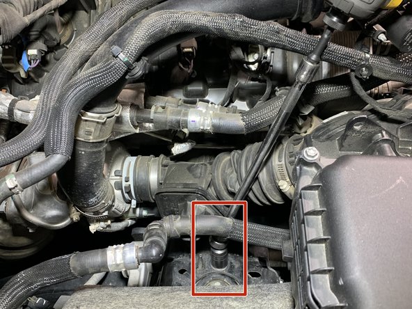
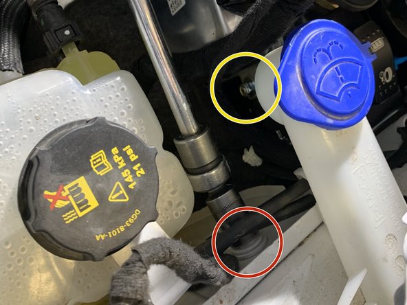
Remove the factory 6mm bolt between the windshield washer reservoir and coolant overflow tank using a 10mm socket/wrench.
-
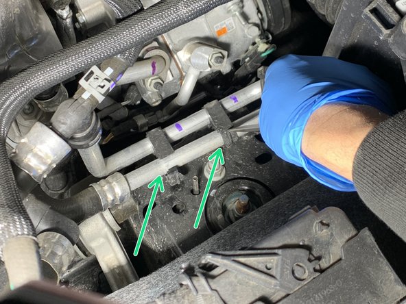
Loosely install the Side Support Bracket to the inner fender and reinstall the factory 6mm fender bolt.
-
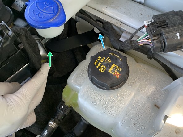
Attach the other side of the Side Support Bracket to the PCM/compressor bracket assembly and secure it using the provided M6x1.0 25mm Carriage Bolt with a washer under the nylock nut.
-
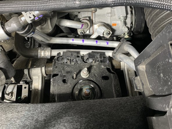
Use a 10mm socket/wrench to torque hardware to 7 lb-ft [9 Nm].
-
-
-
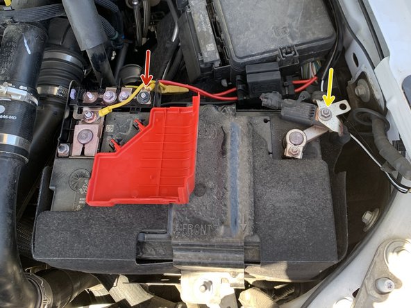
To finish the install, connect the ARB compressor harness power leads directly to the battery according to the ARB Twin Compressor Installation Guide.
-
Three 6 gauge M8 stud size ring terminals are needed to connect the ARB Twin Compressor Harness to the battery terminal ends. (Red/Positive - Yellow/Negative) M8 ring terminal ends are required and do not come with the ARB compressor harness.
-
-
-
Toggle the compressor switch to the on position. The compressor should turn on for a short period of time then turn off.
-
The fan on the ARB Twin Compressor will continue to run until the switch is turned off.
-


![Torque carriage bolt hardware to 7 lb-ft [9 Nm].](https://d3t0tbmlie281e.cloudfront.net/igi/grimmoffroad/yQdxxhWdBJFOe5rX.medium)
![Torque carriage bolt hardware to 7 lb-ft [9 Nm].](https://d3t0tbmlie281e.cloudfront.net/igi/grimmoffroad/kdMksRE4TagNQTEY.medium)

![Use a 15mm socket/wrench to torque the nut to 51 lb-ft [64 Nm].](https://d3t0tbmlie281e.cloudfront.net/igi/grimmoffroad/IIamHesCUmXrp3Ma.medium)
![Use a 15mm socket/wrench to torque the nut to 51 lb-ft [64 Nm].](https://d3t0tbmlie281e.cloudfront.net/igi/grimmoffroad/wPNMrle5oDapylwW.medium)
![Use a 15mm socket/wrench to torque the nut to 51 lb-ft [64 Nm].](https://d3t0tbmlie281e.cloudfront.net/igi/grimmoffroad/XMwkNMUsgoLKYE32.medium)
![Use a 10mm socket/wrench to torque hardware to 7 lb-ft [9 Nm].](https://d3t0tbmlie281e.cloudfront.net/igi/grimmoffroad/Pb2sWo5exHSMIcvn.medium)

Installation is complete!
With any modified vehicle, or any vehicle used offroad, it is a good idea to check bolt torques periodically and visually inspect components regularly.
Installation is complete!
With any modified vehicle, or any vehicle used offroad, it is a good idea to check bolt torques periodically and visually inspect components regularly.
